This thread has been locked.

If you have a related question, please click the "Ask a related question" button in the top right corner. The newly created question will be automatically linked to this question.

IWR6843ISK-ODS: A question about the function of TPS22917DBVR on IWR6843ISK-ODS EVM

Part Number: IWR6843ISK-ODS
Other Parts Discussed in Thread: IWR6843, , TPS22917, IWR1443

Hi  Support team,

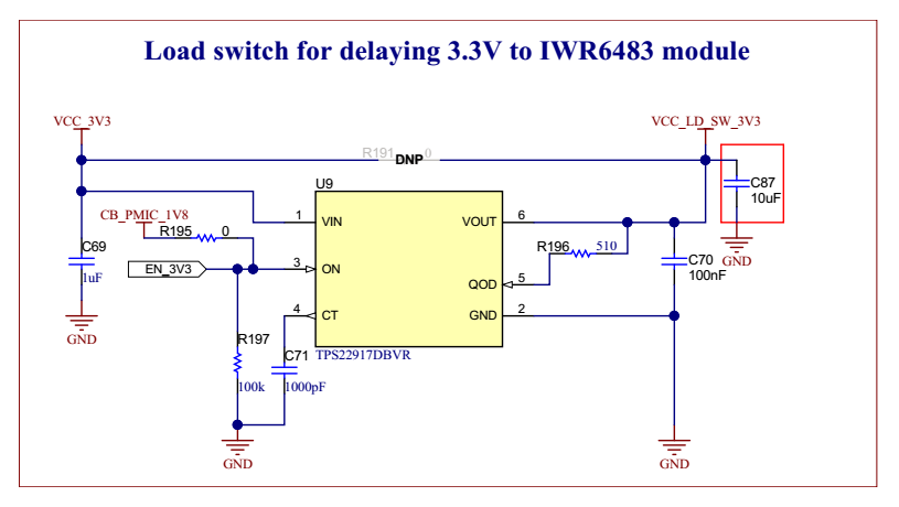
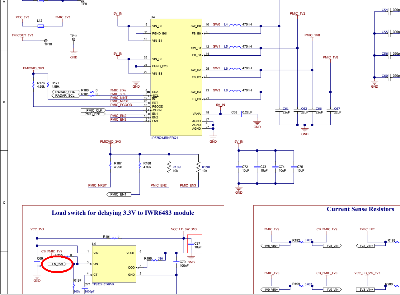
I find there is a TPS22917DBVR used on IWR6843ISK-ODS EVM board, I wonder what the function is for IWR6843 based application?  why does the system need a "Load switch for delaying 3.3V ".

Is there more information for this requirement available? 

Regards

  • Hi,

    Please see section 5.10.1 of datasheet. The TPS22917DBVR is to ensure the 3V3 is delayed until other rails are provided to meet the timing requirment

    https://www.ti.com/lit/ds/symlink/iwr6843.pdf

    Regards,

    Charles O

  • Thanks for your reply.

    Yes, I have studied the IWR6843 datasheet section 5.10.1, the VIOIN is the 3.3V power rail. I believe that TI IWR series sensors would have the similar chip design, so the external power solution may be similar. I designed a project based on iwr1443 and took the sprr254 EVM as a reference. There was a same power sequence requirement in 5.9.1 Power Supply Sequencing and Reset Timing of  iwr1443's datasheet. however there was no a TPS22917 used to generate the 3.3V volatage to VIOIN of IWR1443. On this IWR1443 EVM (PROC010B(003)_Sch), VIOIN is supplied by PMIC 3.3V output through a 0 ohm resistor, the power sequence can not be controlled. So I wonder whether this requirement for is strict for IWR6843 application?  I want to remove this device to reduce the BOM cost, is it OK?

    Regards


  • Hi

    Furthermore, the net EN_3V3 in above screen snapshot is a siingle net in SCH PROC075C(001_IWR)_Sch (swrr165) .  please help to confirm if this is a mistake? who will control the EN_3V3.

    Regards

  • Hi,

    This net is also connected to the PMIC PG(GPO1)

    Regards,

    Charles O

  • Hi

    I double check this connection, I can't find the net in PMIC portion(swrr165 RevC and RevD). It looks CB_PMIC_1V8 are used to enable the TPS22917DBVR . 

    Please help double check which one is correct? Must I connect the EN_3V3 to PMIC PG(GPO1)? If so I must modify my design.

    Regards

    Cunhui


  • HI 

    What about these questions?

    Yes, I have studied the IWR6843 datasheet section 5.10.1, the VIOIN is the 3.3V power rail. I believe that TI IWR series sensors would have the similar chip design, so the external power solution may be similar. I designed a project based on iwr1443 and took the sprr254 EVM as a reference. There was a same power sequence requirement in 5.9.1 Power Supply Sequencing and Reset Timing of  iwr1443's datasheet. however there was no a TPS22917 used to generate the 3.3V volatage to VIOIN of IWR1443. On this IWR1443 EVM (PROC010B(003)_Sch), VIOIN is supplied by PMIC 3.3V output through a 0 ohm resistor, the power sequence can not be controlled. So I wonder whether this requirement for is strict for IWR6843 application?  I want to remove this device to reduce the BOM cost, is it OK?

    Regards

  • Hi,

    if you are using the LP87524 PMIC with the 5V input and 3V3 as one of the output, the timing should/can be set with the PMIC.  The TPS22917 redundancy is not needed.

    Regards,

    Charles O