Other Parts Discussed in Thread: FDC1004
Hi,
I'm doing a capacitive sensing project with FDC2214 and trying to design a circuit for an active shield with an op-amp.
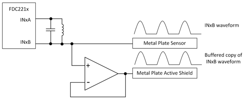
In this advice, https://e2e.ti.com/support/sensors/f/1023/t/641992 the input signal to drive the op-amp is the FDC2214 signal after the LC tank.
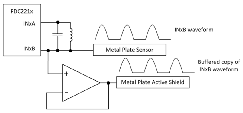
However, in FDC2214 datasheet, 10.1.2 Shield, it says that the shield is a buffered signal of the INxA pin. It seems that the input signal to drive the op-amp is the FDC2214 signal before the LC tank. And I guess this means the following circuit.
Which method is correct to design an active shield circuit with an op-amp? And what's the difference between these two methods?
Thank you,
Mabel


