This thread has been locked.

If you have a related question, please click the "Ask a related question" button in the top right corner. The newly created question will be automatically linked to this question.

IWR6843AOP: No device access via debugger or programmer (UART)

Part Number: IWR6843AOP
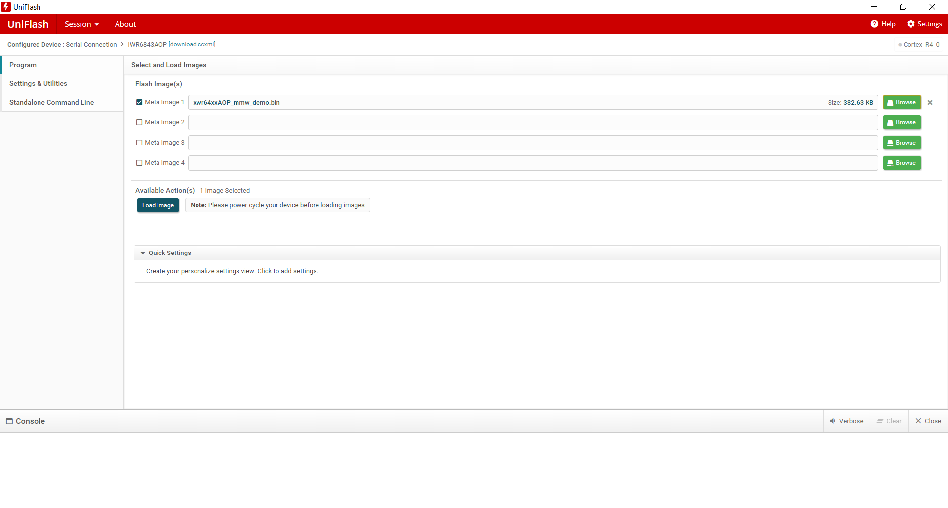
Other Parts Discussed in Thread: UNIFLASH

Hi TI Team,

I designed my own radar board based on the eval kit (https://www.ti.com/tool/IWR6843AOPEVM).

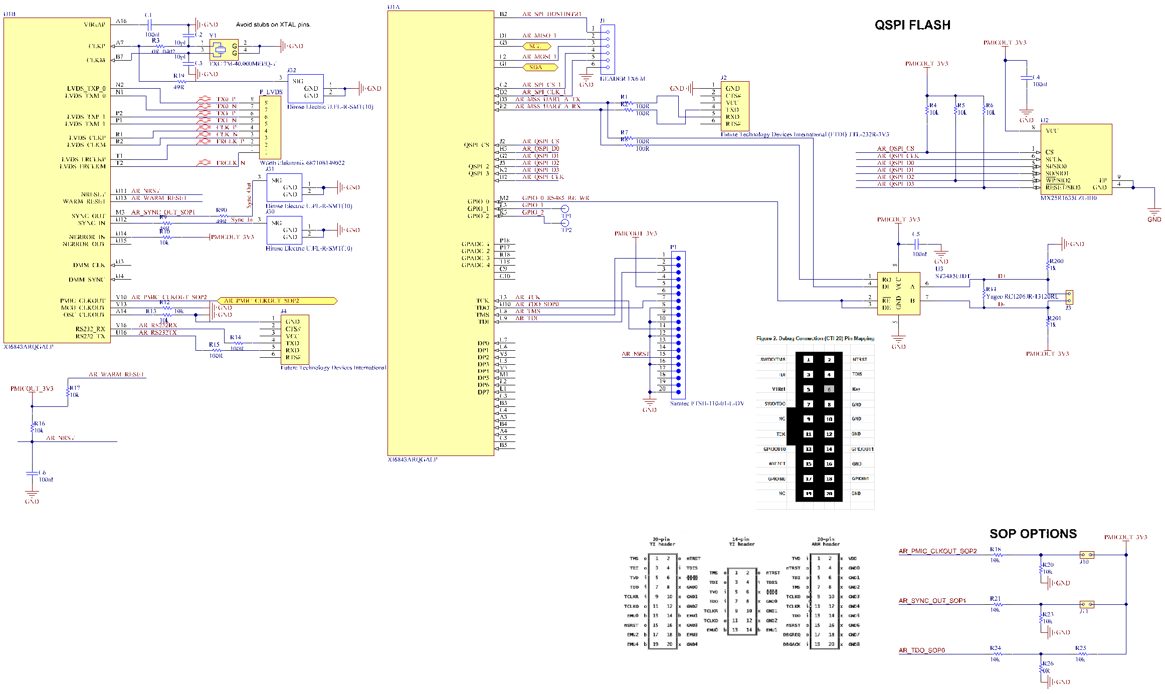
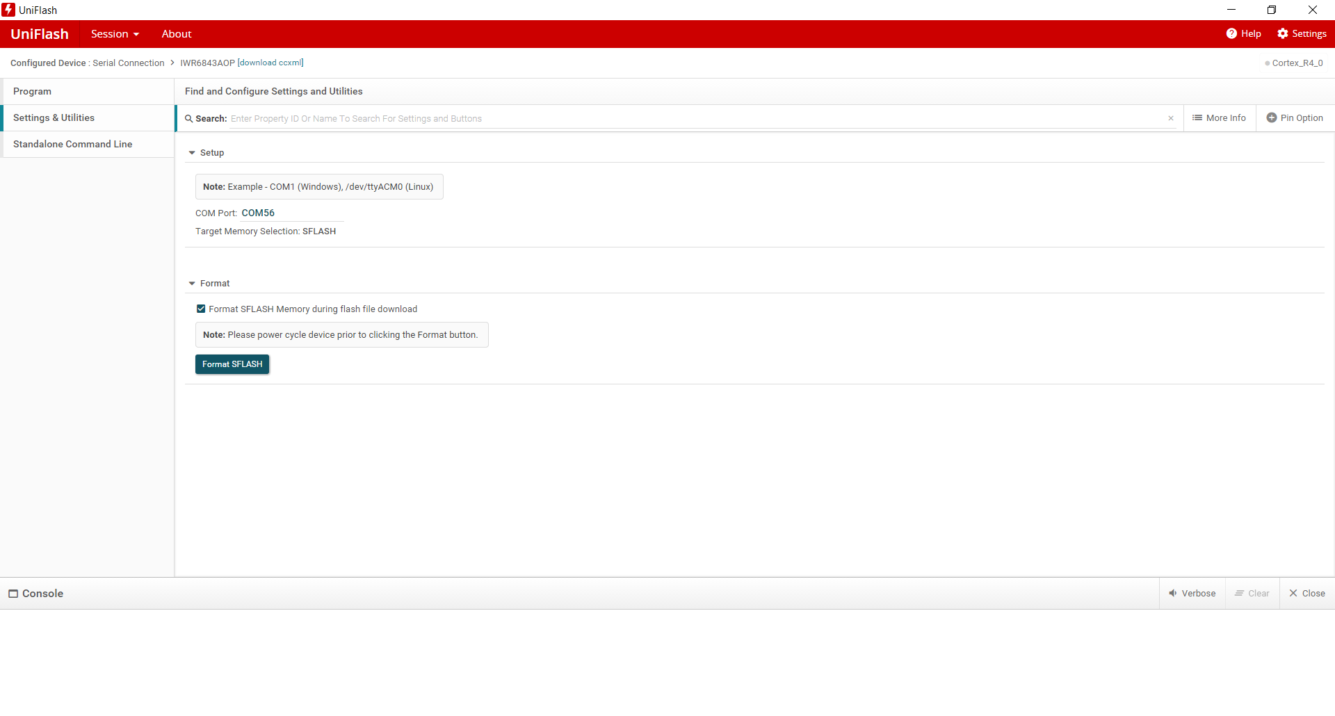
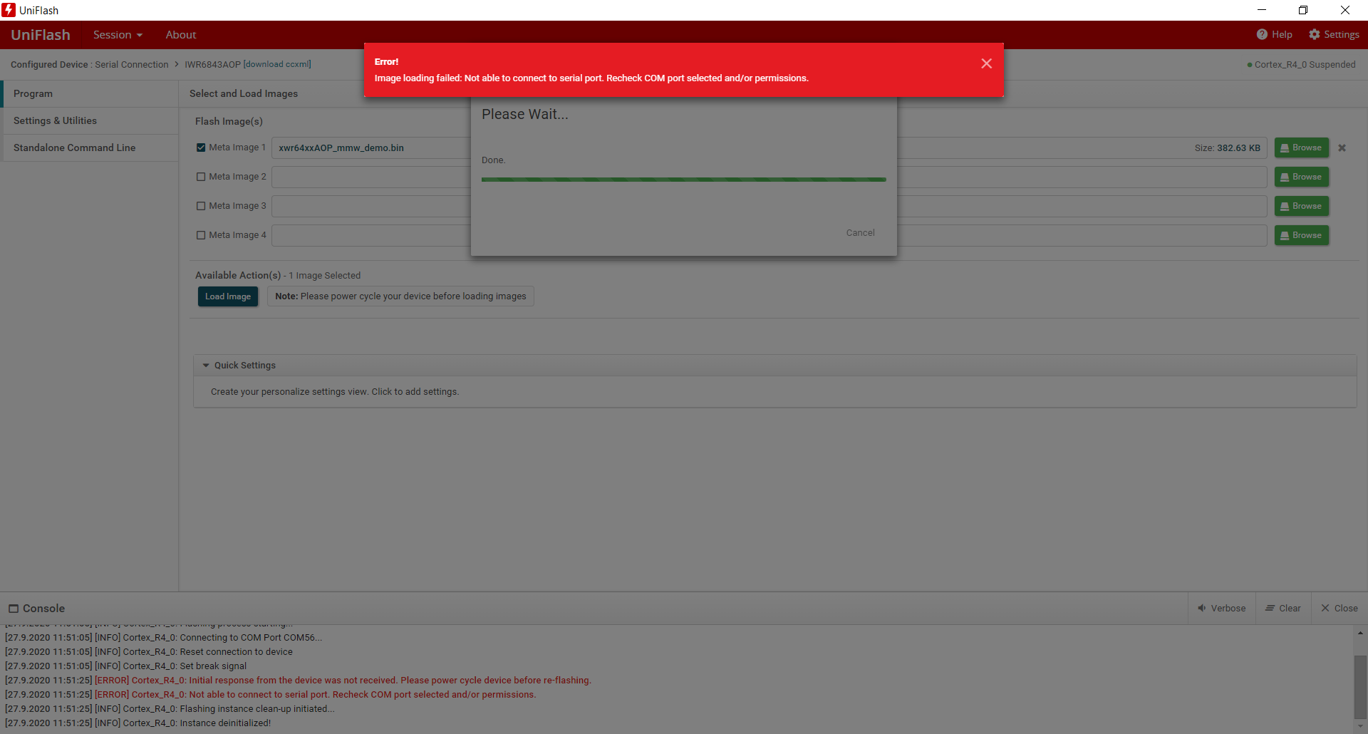
Unfortunately I am not able to program the device (external FLASH) with the JTAG Debugger or the UART programmer.

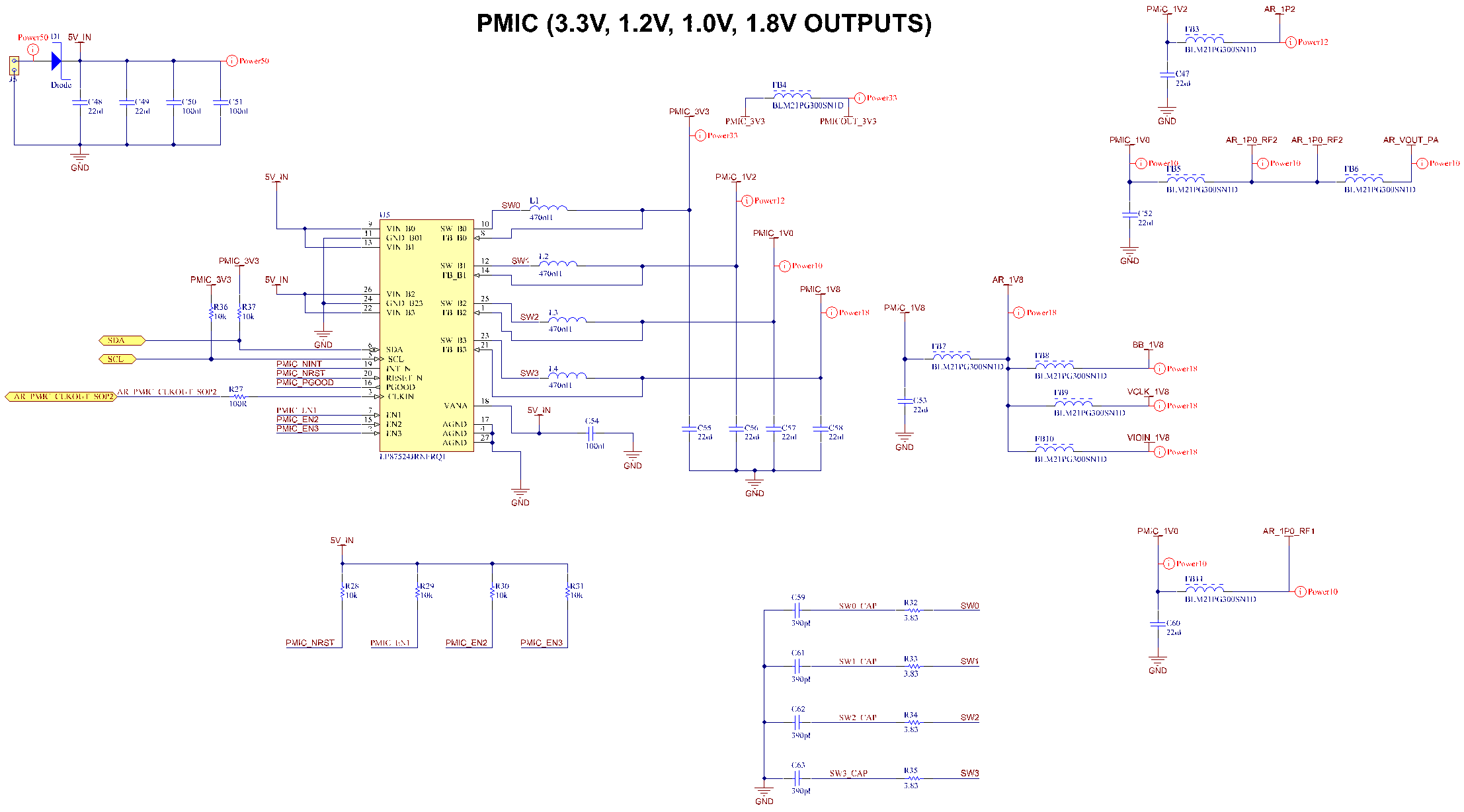
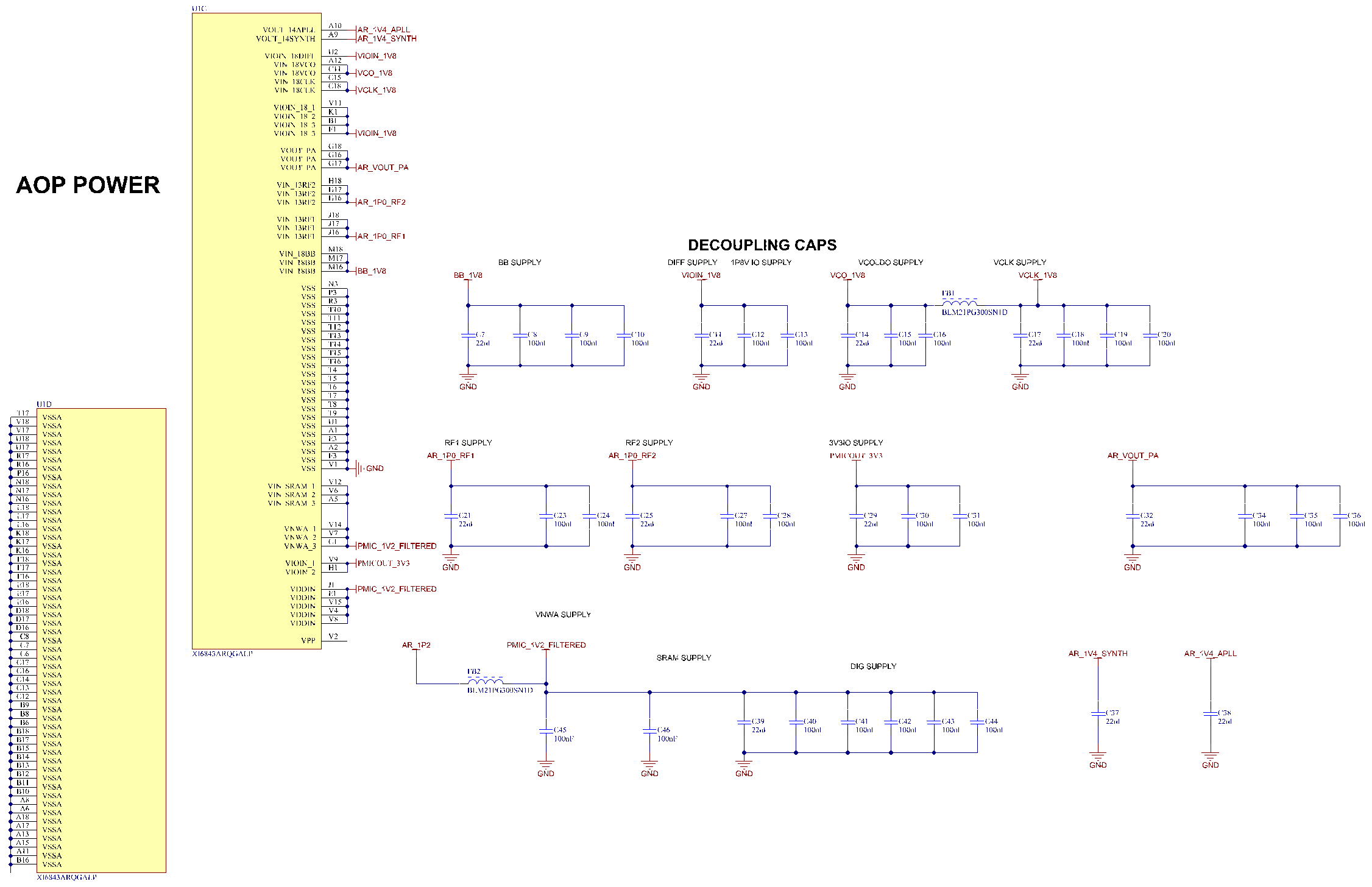
-All voltages are correctly supplied

-The Quartz oscillator is working but at the OSC_CLKOUT is not the clock signal visible

Can you please review the schemtic and give me some advice

  • Hi,

    Please allow few days to get back to you with review comments.

    Regards,

    Charles O

  • Hi,

    attached I send you the PDF schematics.

    Thanks

    TI Radar integrated Antenna.PDF

  • Hi,

    I reviewed the schematic, there is not a lot that needs to change.

    1. VBGAP (A16) should be 47nF, this is an update from 22nF used in the current schematic reference. You 100nF in your schematic, this is not recommended.
    2. Ensure the LVDS trace meet the 100ohms differential impedance recommendations. Also note that this is high speed lines.
    3. Ensure RC timing is such that SOP lines ramp up to steady state before NReset crosses 1.5V

    What is the process you are following for flashing the board? 

    Regards,

    Charles O

  • Hi Charles,

    Unfortunately it did not solve the problem to program or to access the controller via JTAG Debugger.

    To the following points:

    1. i changed the cap at VBGAP to 47nF and measured the voltage to GND -> 0.94V

    2. LVDS traces are not activated, I added a connector but I will not use them

    3. I changed the NReset cap to 22uF

    Nothing has changed on the behaviour to get access to the controller. I made 4 PCBs all have the same behaviour.

    Can you please tell me when  the OSC_CLKOUT has a visiable clock Signal? (right now after powering up)?

  • Hi

    Can you explain how you are you trying to flash the board? what is the setup and the procedure you are following?

    Regards,

    Charles O

  • Hi,

    HW Configuration:

    I connect a FTDI Cable (3.3V version) to the Connector J4

    SOP2 = 1 (high)

    SOP1 = 0 (Low)

    SOP0 = 1 (high)


    SW Configuration:

    To program the device I use the UniFlash 6.1.0.

    After pressing Start the following screen appears.

    I have selected the image C:\ti\mmwave_industrial_toolbox_4_3_2\labs\out_of_box_demo\68xx_aop_mmwave_sdk_hwa\prebuilt_binaries\xwr64xxAOP_mmw_demo.bin

    Then I select the COM Port (COM56) of the connected FTDI Cable

    Then I switched the power supply on.

    After that I go back to Program Screen and press the button Load Image

    Within 20 sec the following screen appears


  • Hello,Michael,

          After the power supply and SOP configuration, it's important to assert a NRESET to register boot mode (Flashing boot mode in this case), Only if the device is in SOP2 mode (Flashing mode then) you would be able to communicate with the device through the Uniflash application.

    Please ensure I/Os are not driven from external interfaces when the VIO supply to the device is not present, i.e. RS232 lines and MSS_logger UART pull up lines. This will cause boot up & reliability problems.

    RS232 UART signal / MSS logger pull up need to be connected to 3.3V VIO supply. And it should not be driven from the external I/O without VIO supply being present on the mmWave sensor board. Otherwise there could be problem by internal protection ESD diode turning on and incorrectly powering the sensor. 

    Crystal pins needs only 4.7pf capacitor, 10pf is on the higher side, Also R19 plus long trance + connector adds additional parasitic capacitor. On the crystal pin no other parasitic should be present. Please remove R19. Also position of R19 need to be reviewed in the layout. Could you please post the layout files? 

    Are you able to connect to the device through the CCS (Code composer studio)?

    NERROR needs external pull-up. If there is a fault in the system NERROR  would be asserted low. you could Probe this line to identify any fault in the system.

    Thanks and regards,

    CHETHAN KUMAR Y.B.