This thread has been locked.

If you have a related question, please click the "Ask a related question" button in the top right corner. The newly created question will be automatically linked to this question.

PGA460-Q1: Power interrupt erases burst pulses number registers.

Part Number: PGA460-Q1
Other Parts Discussed in Thread: PGA460, , MSP-EXP430F5529LP, PGA460PSM-EVM

Hello,

I faced a strange reaction when PGA460 power is interrupted for a short while.
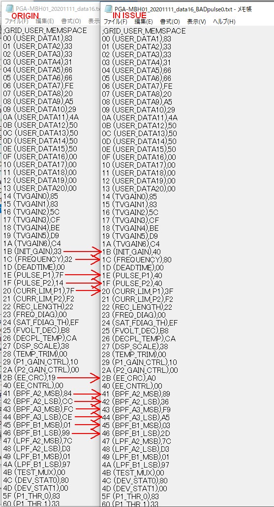
It looses burst pulse numbers of both P1 and P2 however all CRC errors are clear and all other settings are kept correct.

This problem occurred in actual product often and PGA460 keeps running with strange measurement results.
It does not report any error in the first byte of the response UART_DIAG1.
Although, even if error flag was stated, there is no UART command to reload them from EEPROM.

Q1. Does the threshold bulk write command let the PGA460 to reload all registers from EEPROM?

I found this issue by stopping the MCU when strange measurement occurred after power interruption and connect the UART wire from LaunchPad then pressing "Check for PGA460-Q1" button in GUI.
As much as I see errors in GUI by that, VPWR_UV flag in DEV_STAT1 is not stated.
MCU does not read DEV_STAT1 register. So GUI is the first reader of VPWR_UV thus it is not cleared before GUI reads.
There seems to be no communication can notice this issue.

Q2. How should I detect and resque from it?

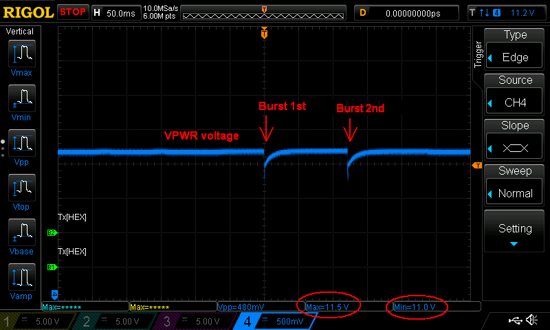
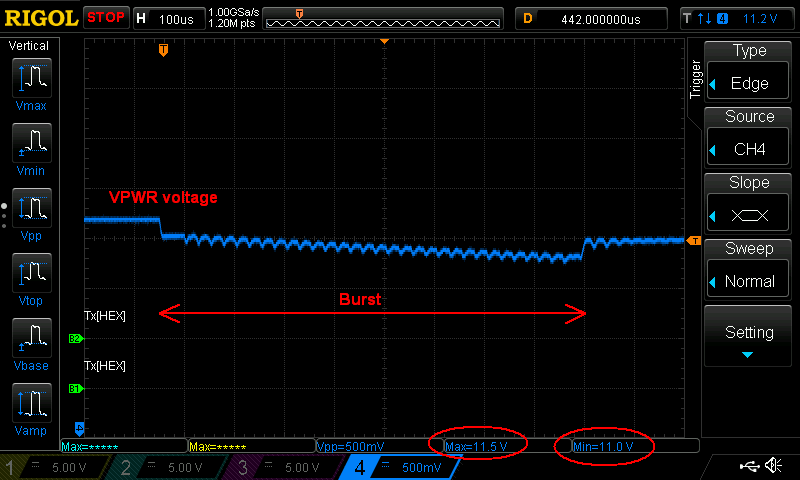
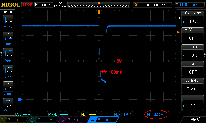
My guess of issue reason is the burst current.
I checked if same register vanishment happens by turning down the power voltage to lower than 6V from 12V slowly but it didn't happen, even though error flags of under voltages and threshold CRC error are stated.
The difference of situation was that I checked it while PGA460 is idle, not bursting.
Then the vanishment is scanned while PGA460 in burst and listen cycle, as I mentioned above. So I guess burst current is causing the vanishment of burst pulses number register values.
It occurres above under voltage, before threshold memory disappears, behind any error flag. 

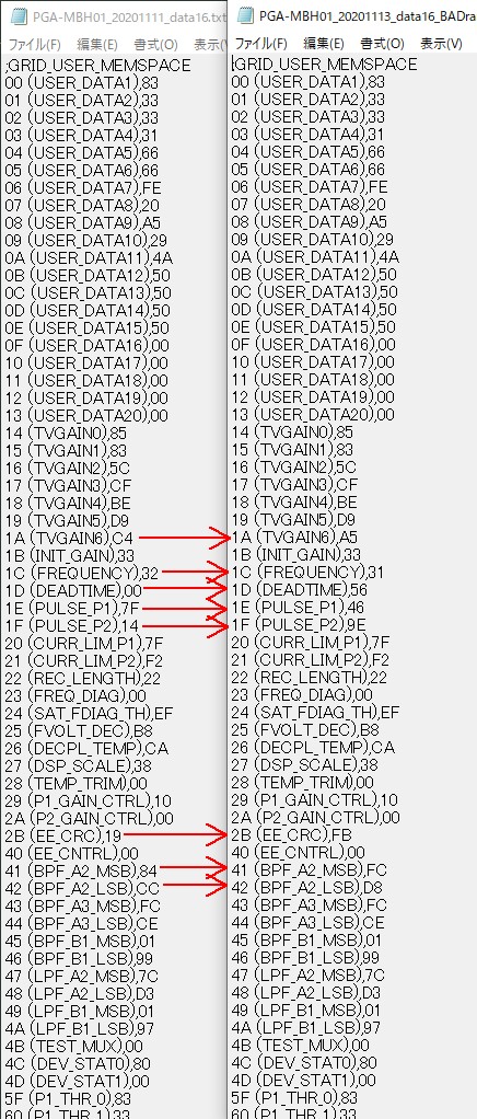
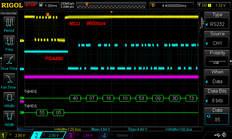
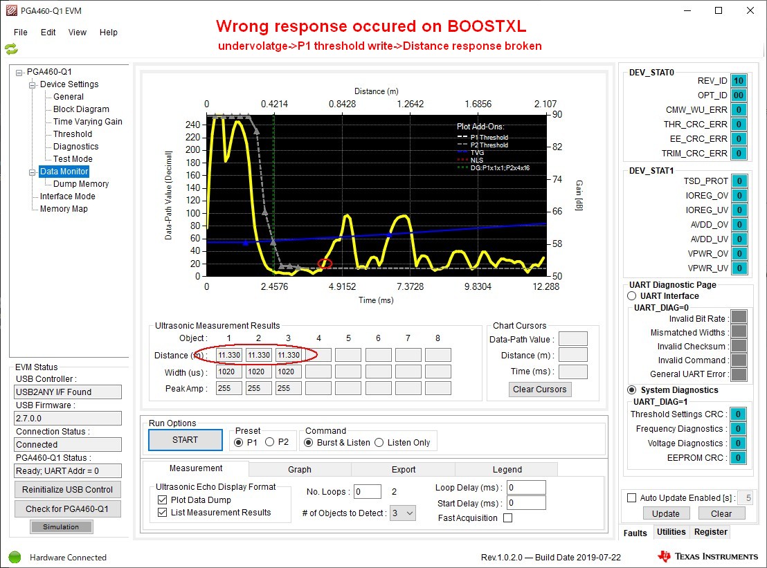
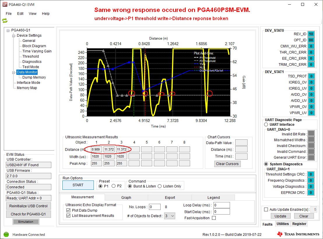
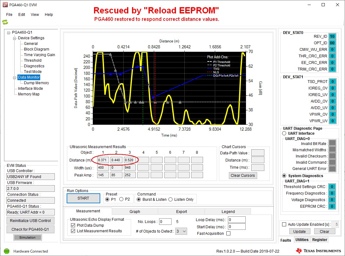
Please trace 3 screen captures.
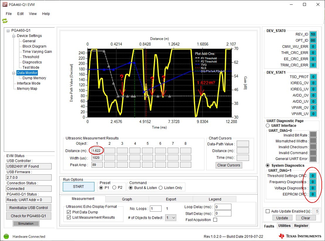
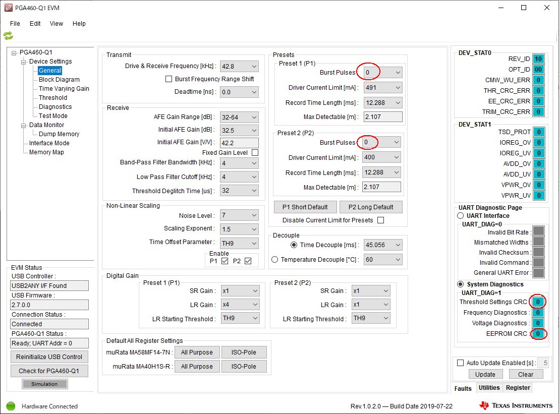
1st, lost burst numbers and no CRC error alarted:

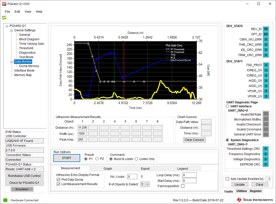
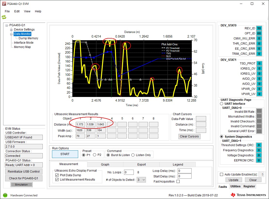
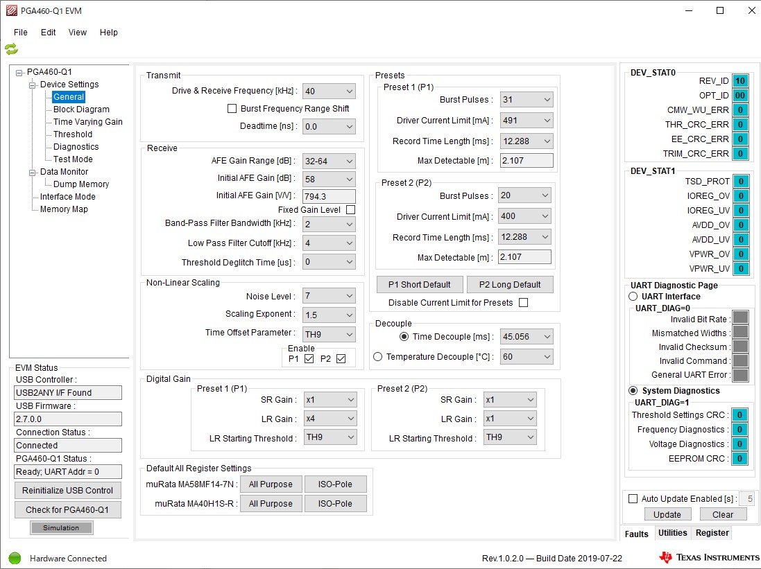
2nd, original correct settings:

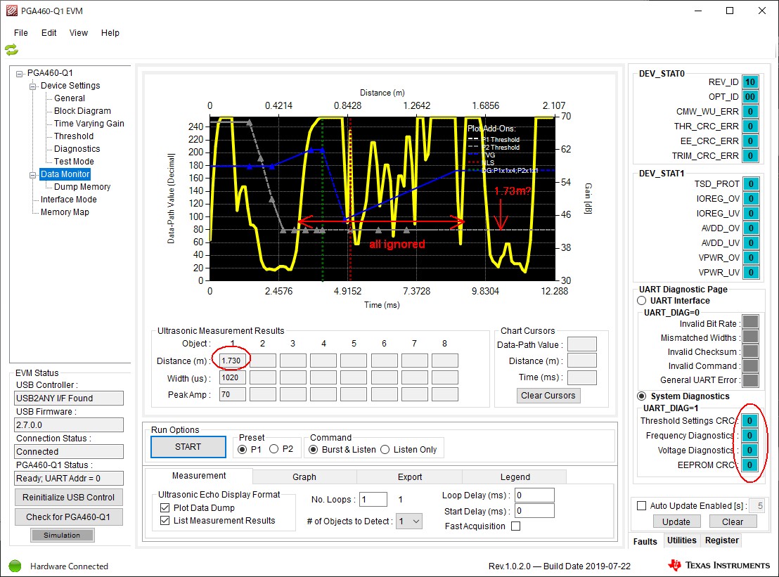
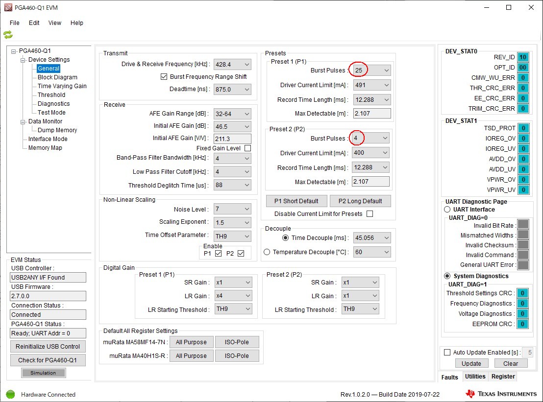
3rd, burst pulses number left random instead of 0 sometimes:

All other values are kept but only burst pules numbers are lost.
Please help.

Best Regards,
Andy

  • Here is more related issue.

    In same power interrupt inspection, more unnoticeable problem happened.
    While placing the bounce object at 0.5m distance, PGA460 started responding object at 1.6m away and that wrong response kept eternally eventhough no error is stated.

    I guess some internal current or leak voltage breaks the register values randomly not only burst pulses.

    Here's the screenshot of wrong measurement response.
    You can see the wave that swings above the threshold line many times before 1.6m but it reports 1.6m as the first detection.

    Screenshot below tells all ignored but unexisting object reported:

  • I saved the memory map from troubling PGA460 and traced with original map.
    There was no difference in them.
    So the problem might be in working registers.

    ;GRID_USER_MEMSPACE
    00 (USER_DATA1),83
    01 (USER_DATA2),33
    02 (USER_DATA3),33
    03 (USER_DATA4),31
    04 (USER_DATA5),66
    05 (USER_DATA6),66
    06 (USER_DATA7),FE
    07 (USER_DATA8),20
    08 (USER_DATA9),A5
    09 (USER_DATA10),29
    0A (USER_DATA11),4A
    0B (USER_DATA12),50
    0C (USER_DATA13),50
    0D (USER_DATA14),50
    0E (USER_DATA15),50
    0F (USER_DATA16),00
    10 (USER_DATA17),00
    11 (USER_DATA18),00
    12 (USER_DATA19),00
    13 (USER_DATA20),00
    14 (TVGAIN0),85
    15 (TVGAIN1),83
    16 (TVGAIN2),5C
    17 (TVGAIN3),CF
    18 (TVGAIN4),BE
    19 (TVGAIN5),D9
    1A (TVGAIN6),C4
    1B (INIT_GAIN),33
    1C (FREQUENCY),32
    1D (DEADTIME),00
    1E (PULSE_P1),7F
    1F (PULSE_P2),14
    20 (CURR_LIM_P1),7F
    21 (CURR_LIM_P2),F2
    22 (REC_LENGTH),22
    23 (FREQ_DIAG),00
    24 (SAT_FDIAG_TH),EF
    25 (FVOLT_DEC),B8
    26 (DECPL_TEMP),CA
    27 (DSP_SCALE),38
    28 (TEMP_TRIM),00
    29 (P1_GAIN_CTRL),10
    2A (P2_GAIN_CTRL),00
    2B (EE_CRC),19
    40 (EE_CNTRL),00
    41 (BPF_A2_MSB),84
    42 (BPF_A2_LSB),CC
    43 (BPF_A3_MSB),FC
    44 (BPF_A3_LSB),CE
    45 (BPF_B1_MSB),01
    46 (BPF_B1_LSB),99
    47 (LPF_A2_MSB),7C
    48 (LPF_A2_LSB),D3
    49 (LPF_B1_MSB),01
    4A (LPF_B1_LSB),97
    4B (TEST_MUX),00
    4C (DEV_STAT0),80
    4D (DEV_STAT1),00
    5F (P1_THR_0),83
    60 (P1_THR_1),33
    61 (P1_THR_2),33
    62 (P1_THR_3),31
    63 (P1_THR_4),66
    64 (P1_THR_5),66
    65 (P1_THR_6),FE
    66 (P1_THR_7),20
    67 (P1_THR_8),A5
    68 (P1_THR_9),29
    69 (P1_THR_10),4A
    6A (P1_THR_11),50
    6B (P1_THR_12),50
    6C (P1_THR_13),50
    6D (P1_THR_14),50
    6E (P1_THR_15),00
    6F (P2_THR_0),83
    70 (P2_THR_1),33
    71 (P2_THR_2),33
    72 (P2_THR_3),31
    73 (P2_THR_4),66
    74 (P2_THR_5),66
    75 (P2_THR_6),FE
    76 (P2_THR_7),20
    77 (P2_THR_8),A5
    78 (P2_THR_9),29
    79 (P2_THR_10),4A
    7A (P2_THR_11),50
    7B (P2_THR_12),50
    7C (P2_THR_13),50
    7D (P2_THR_14),50
    7E (P2_THR_15),00
    7F (THR_CRC),95
    EOF
    

  • Hi Andy,

    After you observe this issue, could you go to the “Memory Map” screen on the GUI and Click the “Read All” button? After doing this, do you see the the P1 and P2 pulse values return back to normal when you look back at the “General” screen again? If not, do you also see that the values of the “Pulse_P1” and “Pulse_P2” registers in the “Memory Map” screen are also wrong?

    Also, after you see this issue, can you try removing power to the board for a couple of seconds and then powering it up back again? After doing this, do you see that the pulse values return back to normal?

    Thank you,

    Mekre

  • Hi Mekre,

    Step1. After you observe this issue, could you go to the “Memory Map” screen on the GUI and Click the “Read All” button? After doing this, do you see the the P1 and P2 pulse values return back to normal when you look back at the “General” screen again?

    Ans1. No, both P1 and P2 pulse values kept 0 in the "General" screen. I clicked "Check for PGA460-Q1" then "Read All" so the Memory Map is really read from physical PGA460 to GUI and it showed 0 burst pulses.

    Step2. If not, do you also see that the values of the “Pulse_P1” and “Pulse_P2” registers in the “Memory Map” screen are also wrong?

    Ans2. Memory map also shows wrong pulse values such as PULSE_P1 01000000, PULSE_P2 01000000.

    Step3. Also, after you see this issue, can you try removing power to the board for a couple of seconds and then powering it up back again? After doing this, do you see that the pulse values return back to normal?

    Ans3. Yes, pulse values return back to normal. So values in EEPROM is not affected but values in registers are over written random.

    Thanks,
    Andy

  • Here's memory map trace of the PGA460 in issue, burst pulse values turned to 0, and origin.


    It tells values are overwitten not only burst pulse but also gain, frequency, EE_CRC and BPF.

    Interesting point is EE_CRC changed. I guess it is generated by PGA460 core.

    The wave form of the PGA460 in this issue is below.

  • Mekre, please tell me if there is a hidden UART command to reload EEPROM to registers.
    I need to finish this product tomorrow.

    If there is such command, I will send it every burst cycle that wipes all troubles away.

    Best Regards,
    Andy

  • Hi Andy,

    From the GUI, you can reload the EEPROM by going to the “Test Mode” page and clicking the “Reload EEPROM” button. After doing this, you may have to do a “Read All” within the “Memory Map” window in order to see the updated values of the register.

    The Reload EEPROM command is done by setting the EE_RLOAD bit in the EE_CNTRL register. To do this in your software, you can send the following byte sequence through the UART: 0x55, 0xA, 0x40, 0x02, 0xB3.

    Regards,

    Mekre

  • Mekre, thanks but the result I see through GUI is suspicious...

    I followed your GUI reload eeprom method to the issued PGA460 which memory is as below:

    I did "Check for PGA460-Q1", "Read All", "Reload EEPROM", "Read All" then memory map showed all "00". It is very strange.
    Then I did it 1 more time "Reload EEPROM", "Read All". It showed seemingly correct values in memory map.
    And I went to Data Monitor to see if it really function. Surprisingly, record length became wrong, infact REC_LENGTH register had not bad value before reloading as above memory map tells.
    Then I clicked "Reload EEPROM" again. Then it functioned correctly finally.

    My PCB design flows UART signals smooth. And I tie down the MCLR of MCU PIC16F1827 by jumper pin. So PIC UART ports are in high impedance.

    If this reload unstable result is not GUI sequence problem, it seems I need to reload twice at least to keep PGA460 functioning.

    I will check the PGA460 power ripple but I followed PCB design indication very carefully.
    As a matter of fact, PGA460 is in idle while receiving "Reload EEPROM" command so that power ripple may not appear that time.

    Should I add "Reload EEPROM" twice?

    Best Regards,
    Andy

  • Here's my circuit. The power source is the battery of heavy industry vehicle. The power voltage varies 10V - 30V.

    PGA460relativecircuit.pdf

  • Here's VPWR voltage ripples in normal situation. I think it is not bad.

    Close look.

  • About UART signal consistency between LaunchPad and PGA460 on PCB.
    I found there is strong crosstalk appears in GUI communication wire from LaunchPad. But that seems not disturbing the communication. Response signal is clear.

    Here is UART signals between MCU and PGA460.

    I realised diodes, D3 and D4, in two PGA460 response wires are not needed. They just can be tied together. They are pulled up to 3.3v through 100Kohm.
    It seems PGA460 TX port is high impedance at idle, that shields confliction to other PGA460s.

    Best Regards,
    Andy

  • Hi Andy,

    I see extra connections on your UART TX and UART RX lines that are not present in the PGA460 EVM. Do you see the same issues when you use the PGA460 EVM with the MSP-EXP430F5529LP instead?

    Can you also try removing R11, D3, and D4 on your board to see if it makes a difference? You may have to add an additional connection to make sure that the PGA460 TXD pin is connected to your microcontroller after you remove D3 and D4.

    Regards,

    Mekre

  • I checked PGA460 EVM with MSP-EX430F5529LP and no register overwrite could be found BUT it also starts to respond wrong distances.


    And PGA460PSM-EVM also does same.

    I removed R11, D3 and D4 and PGA460 still remains the problem. It is simply same with EVM.
    I took every memory map of PGA460 EVM in issue and they all had no mis-match to the original map. Now problem is outside of registers.
    Then the problem origin becomes deeper. If problem was in register values, it is visible and can be rescued by reloading it.
    But when it is invisible and untouchable, problem becomes uncontrollable since PGA460 does not have "reset" command.

    Although, "Reload EEPROM" command looks recovering the whole issue, not only registers but also program memories, I am curious if it also reloads program memories.
    As much as I see the distance values of post-issued PGA460 rescued by "Reload EEPROM", distance values are recovered as below.

    In issue.

    Recovered.

    So, for concerning undervoltage or close undervoltage, PGA460 needs "Reload EEPROM" command to every burst&listen cycle.
    I am not sure if the undervoltage flag was set all the time PGA460 derails by low power. Even if undervoltage flag is set, there seems no command to reset whole PGA460.
    Hopefully "Reload EEPROM" recovers all program condition.

    So then, I will try adding "Reload EEPROM" to every burst cycle. That command may need 10ms wait as PGA460 needs 10ms at boot up.
    I worry if there was any bad point of reloading EEPROM uncountable times. Does reloading EEPROM uncountable times destroy the PGA460 system?

    Best Regards,
    Andy

  • This is the power interrupt waveform that PGA460 malfunctions.

    It is same on EVM.

    Problem seems to be "Internal Power-on Reset" does not work to the undervoltage issue.

    And this comment in data sheet does not really act as so.

  • Hi Andy,

    Thank you for the plot.  Do you have similar plots for IOREG and AVDD as well?

    Regards,

    Mekre

  • Hi Mekre,

    No, I don't have plots of there. Now PCB is gone to my client. I will make another in 3 weeks.
    Regarding IOREG and AVDD are poured from VPWR, 100ms is enough to drop them to same low voltage for similar duration.

    Best Regards,
    Andy

  • Hi Andy,

    It is recommended that the PGA460 has a stable power supply for operation. Our recommendation is to try to stabilize the power to the device to prevent the power interruptions that you are noticing.

    Regards,

    Mekre

  • Thanks Mekre, you are right. I understand about the power stability base of IC usage.
    But this problem is very similar to the car accessory power delivery situation.

    When car key is on, accessory power is delivered once.
    And while starting the engine, accesorry power is disconnected for a short while.
    Then accessory power comes back soon after engine is started.

    When my system had two 470uF capacitors in power line, PGA460 register values had gone random, burst pulse overwritten to 0, and responded wrong distance values.
    I disconnected those capacitors not to flow into PGA460 then register values kept good but system still responded wrong distance values.
    PGA460 simply derails by its default 100uF capacitor in VPWR.

    Both large and small stabilizing capacitors did not help.
    I know you meant stabilizing the power as to keep tight power source connection.

    I really count on this IC. I am planing to promote new product with this PGA460 to my major client.
    Then I want you to give it more reliability please. This is a very good IC.

    Best Regards,
    Andy
     

  • Hi Andy,

    As the datasheet excerpt you posted indicates, the performance of the device is not ensured if the voltage on the VPWR pin is less than 5 V; however, perhaps you can try to make the system a little more robust by reloading the shadow registers from EEPROM after this interruption, as we were previously discussing. After doing this, you should also rewrite the threshold values.

    Here are some potential options for detecting the power interruption:

    • Perform a calculation of the EEPROM and threshold CRCs and then compare it to the EEPROM and threshold CRC registers. If there is a mismatch, perhaps this could indicate that the power interruption has occurred.
    • Divide down the VPWR voltage using a voltage divider and then feed this divided down voltage to the inputs of the microcontroller’s GPIO. The voltage divider should be selected so that the set voltage interruption voltage level triggers a port interrupt on the microcontroller.
    • Configure the microcontroller’s ADC to measure its internal supply voltage, assuming this option is available on the microcontroller. If the microcontroller’s power supply is better regulated than VPWR, please note though that it is possible that you might not be able to sense power interruptions on the microcontroller’s voltage range or the indication of power interruptions could lag compared to when these interruptions are seen on VPWR.

    Please note that you would need to verify the feasibility of these options for your particular system.

    Regards,

    Mekre

  • Hi Mekre,

    Rewriting the threshold values along with Reload EEPROM is a very good info.
    And VPWR voltage divider and ADC are good idea.

    Thank you very much for your support.
    TI is a great company.

    Best Regards,
    Andy