This thread has been locked.

If you have a related question, please click the "Ask a related question" button in the top right corner. The newly created question will be automatically linked to this question.

TMP108: Non-monotonic signal edge for I2C signals on TMP108

Part Number: TMP108
Other Parts Discussed in Thread: TMP1075

Hi, 

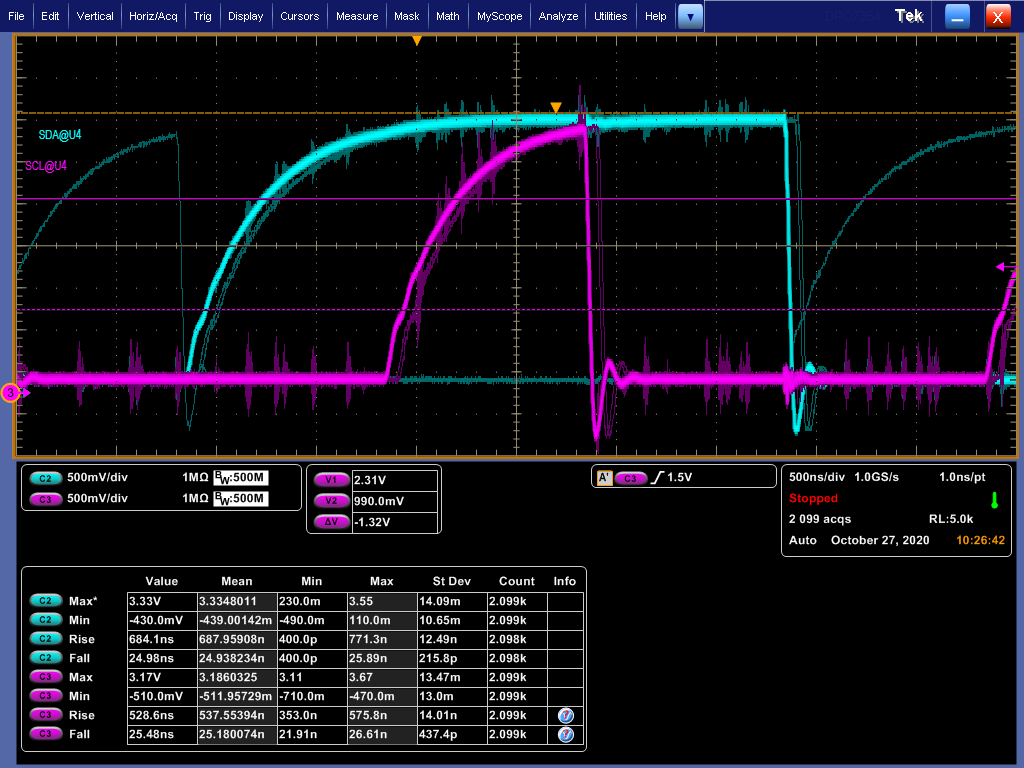
I am currently using the TMP108 temperature sensor. On my board, there will be noisy from other traces that coupled into the I2C signals (SDA, SCL). The noise can happen anytime during the signal (rising edge, falling edge, high state, low state). My concern is will this noise coupled into I2C signal, results in non-monotonic signal around the input threshold level (Vih = 2.31V, Vil = 0.99V @ Vcc = 3.3V).

Here is a screenshot of the waveform with infinite persistence mode turned on.

Here are some of my questions:

  • When the noise happens during the signal edge, it can cause non-monotonic signal and potentially read the wrong logic level. How does this non-monotonic signal affects the I2C signal?
  • Is there any hysteresis within the input of the TMP108 temperature sensor, such that the non-monotonic signal is not an issue?
  • Based on I2C specification, the SDA data must be stable when SCL is high. How does the TMP108 latches data internally?
  • Does the TMP108 device reads the data when SCL is logic high for some time and latch the data?
  • Or it latch the data during rising edge of SCL?
  • If it is latching data during rising edge, then potentially the non-monotonic signal will corrupt the communication, and read wrong data.
  • With the noise coupled into SCL signal and create the non-monotonic rising edge, how will that affect the timing, as the setup/hold time might be changing due to the bad SI signal?
  • Does the TMP108 uses the SCL clock to perform some internal operation, such that this clock must be fully monotonic?
  • Lastly, the TMP108 allows 4 different addresses with the A0 pin connection. Now I am using 4 of them. If the signal to the A0 pin is coupled with this noise (SDA, SCL), will that affect my TMP108 addressing?

Thanks.

  • Hi,

    Thank you for posting and welcome to the Sensing forum.

    Section 6.5 of the TMP108 datasheet specifies the device input logic high and low levels.

    I am checking with our design team in order to be able to answer the specifics of your other questions, and I will update you as soon as I have that information.

    Best regards,

    Nicole

  • Hi, 

    I was able to get more detailed information from the design team.

    Lee Zhi Xian said:
    • Is there any hysteresis within the input of the TMP108 temperature sensor, such that the non-monotonic signal is not an issue?

    Yes, there is hysteresis on the input of the TMP108.

    Lee Zhi Xian said:
    • Does the TMP108 device reads the data when SCL is logic high for some time and latch the data?
    • Or it latch the data during rising edge of SCL?

    The data is latched at the rising edge of the clock. There is a filter on the clock line; if the glitch is smaller than the filter time it will be filtered out.

    Lee Zhi Xian said:
    • If it is latching data during rising edge, then potentially the non-monotonic signal will corrupt the communication, and read wrong data.

    Yes, if noise is able to create multiple edges from the same edge it will give miscommunication and incorrect data.

    Lee Zhi Xian said:
    • Lastly, the TMP108 allows 4 different addresses with the A0 pin connection. Now I am using 4 of them. If the signal to the A0 pin is coupled with this noise (SDA, SCL), will that affect my TMP108 addressing?

    Adding a filter on the pins and slowing down communication can help if the environment is too noisy.

    Best regards,

    Nicole

  • Hi Nicole,

    Thanks and appreciate your help to check with the design team.

    • You mentioned that there is hysteresis on the input pin. Does this apply to both SCL and SDA?
    • There is a filter on the clock line. Is this a separate filter on top of the hysteresis on the input pins?
    • What is the filter time that I should make sure the noise doesn't exceed and gets filtered out?

    Good to know that the data is latched during rising edge of clock. So care must be taken to ensure the clock is monotonic.

    On a side note, if let say there is a communication or data corrupted while communicating with the temperature sensor and potentially put the sensor's state machine into bad state. Is power cycle the only way to reset the TMP108?

    Thanks.

  • Hi Lee,

    Lee Zhi Xian said:
    • You mentioned that there is hysteresis on the input pin. Does this apply to both SCL and SDA?
    • There is a filter on the clock line. Is this a separate filter on top of the hysteresis on the input pins?

    Yes, there are input filters on both SDA and SCL.

    Lee Zhi Xian said:
    • What is the filter time that I should make sure the noise doesn't exceed and gets filtered out?

    The TMP108 supports the transmission protocol for both fast (1 kHz to 400 kHz) and high-speed (1 kHz to 3.4 MHz) modes. There is more information on timing definitions in section 6.6 of the datasheet. 

    According to I2C specification (www.nxp.com/.../UM10204.pdf) Table 9, footnote [8] the input filters are designed to suppress noise spikes of less than 50 ns. The design team will need to confirm that this is the case for the TMP108. 

    Lee Zhi Xian said:

    On a side note, if let say there is a communication or data corrupted while communicating with the temperature sensor and potentially put the sensor's state machine into bad state. Is power cycle the only way to reset the TMP108?

    The TMP108 can also be reset with the general call reset command, which is detailed in section 7.3.7 of the datasheet. 

    Additionally, what value pullup resistors are you using? If you are able to share a schematic or layout we can further assist with any noise issues.

    Best regards,

    Nicole

  • Hi Nicole,

    Thanks for pointing out the specs from I2C user manual. This is really useful doc to me.

    • Input hysteresis
      • According to the I2C manual, there will be minimum 0.5Vdd of hysteresis on Schmitt trigger input and previously you have confirmed there will be hysteresis on the inputs. May I know is the value same as 0.5Vdd?
      • For reference, I tried to look around "Digital Temperature Sensor product list", for the TMP1075, it does clearly specify the input voltage hysteresis is 0.6V.
      • So, can you help to check with design team on this number, and possibly update it into the datasheet to be clearer?
    • Input filters
      • According to the I2C manual, both the I2C inputs reject noise spikes of less than 50ns.
      • I refer back the TMP108 datasheet, section 7.3.1 mentions "SDA and SCL pins feature integrated spike-suppression filters and Schmitt triggers to minimize the effects of input spikes and bus noise". This confirms the filter available in this part. But can you help to confirm is the value 50ns?

    Regarding the pull up resistor, I am currently using 1kΩ pull up. 

    Really appreciate a lot for your help. Thanks. :)

  • Dear Lee - 

    is there some issue with the device that you are having? In the scope shot its very clear you either don't have strong enough pullup on I2C line or too much load cap, or both. I would recommend you fix that first, then see if you have additional issues. 

  • Hi Lee,

    Thank you for your patience. I have reached out to our design team to confirm both the input voltage hysteresis and the exact value of noise spikes that will be suppressed.

    Best regards,

    Nicole