This thread has been locked.

If you have a related question, please click the "Ask a related question" button in the top right corner. The newly created question will be automatically linked to this question.

DRV425: Precision measurements of Earth's magnetic field

Part Number: DRV425
Other Parts Discussed in Thread: ADS1115,

Hello,

I'm a Physics professor at UNH working in the field of space plasma physics and space weather.  In this field, we measure variations of currents in the ionosphere and magnetosphere (>100km above ground) with ground magnetometers. There are currently about 300 stations worldwide and they are generally very expensive to set up and operate.  We are interested in variations of Earth's field from 1 nT to 100s nT.  Ideally we like data at 1Hz but 1 minute data are also useful for many applications.

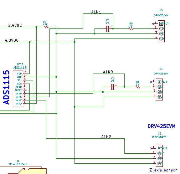
We have developed a station design consisting of 3xDRV425EVM, ADS1115, and Particle Photon/Boron uP.  We have installed one station in Athabasca/CA right next to a high-quality fluxgate for comparisons.  The results are actually quite impressive.  We sample at a high rate (128Hz) and average to 10s in those plots.  Note that these staions are remote, so we don't care about extenal noise.  Also sensors are buried in the ground, so T stability is not important.  Likewise, slow drifts (>1h) don't matter.  But it would be great if we could reduce the noise.  I wonder if you could give us some advice on how to reduce noise.

1.  Is there an optimal sampling strategy?

2.  Would a change of Rshunt/sensitivity help?

3.  Would RL filters on V_out help?  If so, how should they be dimensioned?  Obviously fc~1Hz, but that could be achieved with different RC combinations that may have advantages or drawbacks?

4.  Averaging multiple sensors would probably help.  Have you seen any design that puts multiple DRV 425 on one board?  Using the EVM boards would be more costly than we like and unfortunately we don't have facilities to mount the QFM chips.

Any help would be very much appreciated.

Best regards -- Jimmy Raeder

BTW, I know something about fluxgates, and the 425 is really impressive.  Any DRV426 in the making?

pl-p010-10s-20201221-I1.pdf

  • Joachim,

    Our DRV425 expert Javier is out on holiday today and tomorrow, as TI observes New Years as a holiday. I have made him aware of your questions, and we will get you some answers Monday when we return to the office. 

    In the meantime, there is some great information regarding BW vs. noise for the DRV425 in this forum post

    Also, regarding your question for designs incorporating multiple devices, the DRV425-BUSBAR-EVM, uses two DRV425's mounted opposite to each other to perform differential measurement. This is the only option I know of where multiple sensors are configured.

    We will follow up with you shortly after the holiday

  • Hello Jimmy,

    Thank you for your background information.

    I will go through your questions one by one.

    1.   At this low frequency you normally will not get to the ~250Khz of the internal clock that is activating the flux-gate probe internal.  Other than that the noise can be limited by more sampling and averaging.  I want to make sure what RC values you are using to connect to the ADC.  You want to make sure your load does not cause any issues.  Share your values and I can give you feedback.
    2. You can increase the Rshunt value but most of the noise is coming from the flux-gate noise source.  The Rshunt will limit your range but could help a little.  I would not expect much.
    3. I sort of mentioned in item 1.  The DRV425 Vout and Vref Out cannot drive a large capacitance.  Make sure your resistor is larger.  I will look at the output impedance and give you a resistor value. Make sure you are measuring the Vref voltage so that if it does drift your measurement also drifts the same way.
    4. Even with mounting you will get variation in placement from both the inside of the die in the package and layout/assembly the exact field angle will not be exactly the same.

  • Hi Javier,

    Happy New Year and thanks so much for your help.

    If I read your email correctly there are only two viable options:

    1.  higher readout frequency and more averaging.  We’ll try that.  It may require a different ADC.  Is there an ADC you would recommend?
    2.  RC filter.  Good to know that there are limits on C that we should observe. 
         It would be very helpful to know a good set of R and C values that will give us a roughly 1 Hz edge/cutoff.

    Looking forward to hear from you again.

    Thanks — Jimmy


    --------------------------------------------------------------------------------------------------
    Joachim (Jimmy) Raeder
    Professor of Physics, Department of Physics & Space Science Center
    Chair of graduate admissions
    University of New Hampshire
    245G Morse Hall, 8 College Rd, Durham, NH 03824-3525
    voice: 603-862-3412  mobile: 603-502-9505  assistant: 603-862-1431
    e-mail: J.Raeder@unh.edu
    WWW: squirrel.sr.unh.edu/.../index.php
    --------------------------------------------------------------------------------------------------


  • Hello Jimmy,

    I think the noise of the front end flux-gate will be you biggest issue.  I have a noise analysis describe what I did to estimate it.  8561.DRV425 Noise Analysis.pptx

    The averaging will decrease the bandwidth so with the combination of your RC filter and averaging you should get to the lowest noise possible from the device.

    What I meant about the RC is the if the series resistor is not large enough you could have issues.  So please make sure you have a large enough R.  I would assume greater than 1kΩ.  

    The RC filter should not be large enough that the ADC can sample it.  The RC should be larger than the sampling rate.  The RC filter should allow for the ADC to refresh before its next sample.  See "9.3.2 Analog Inputs".  The RC does not need to filter all the bandwidth as the averaging will further reduce the bandwidth of the signal.  Also from ADS1115 datasheet "Therefore, use a first-order RC filter with a cutoff frequency set at the output data rate or 10x higher as a generally good starting point for a system design."

    I would recommend you measure Vout with respect to the RefIN pin to avoid any drifts with Vref.

    Make sure you look at the drifts that in the datasheet for the DRV425.  The most concerning for you are PSRR and temperature drift.  

  • Hi Javier,  thank you very much.  I’ll keep you posted when we get results. — Jimmy


    --------------------------------------------------------------------------------------------------
    Joachim (Jimmy) Raeder
    Professor of Physics, Department of Physics & Space Science Center
    Chair of graduate admissions
    University of New Hampshire
    245G Morse Hall, 8 College Rd, Durham, NH 03824-3525
    voice: 603-862-3412  mobile: 603-502-9505  assistant: 603-862-1431
    e-mail: J.Raeder@unh.edu
    WWW: squirrel.sr.unh.edu/.../index.php
    --------------------------------------------------------------------------------------------------


  • Hi Javier,

    My name is Juan, and I am working with Prof. Jimmy in this project. We have implemented the RC filter with the next specifications

    R=2.2 Kohms

    C= 47x10-9 F

    Fc=1539 Hz

    Gain for ads1115 = 1.024V

    Impedance for ads1115 @ 1.024 = 2.4Mohm

    Sampling frequency = 128 Hz

    To compare the effects of this low pass filter on the measurements, I aligned two DRV425 sensors in the same direction one with the filter and the other without. In theory, they should measure the same magnetic field but they are slightly different because of the embedded sensors offset. At this stage the offset is not very important, however something that has been brought to my attention is that I am measuring some kind of square wave pulses in both sensors (see figure 1, s1 (sensor with filter), s2 (sensor without filter) please ignore s3 and B). We have several of these modules with the same characteristics in different locations to measure Earth's magnetic field and some of them also show these square pulses. Some of them are in the lab under very controlled environmental and instrumental parameters (e.g., constant power, temperature, etc) and others on the field with Li-ion batteries and cold weather (figure 2, example of good records). In any case both of them show the same pattern, so I would discard any power, low pass filter or temperature problem. Based on this, my question is if do you know what could be the factor that trigger this behavior on the DRV425?

    Thanks in advance for your help,

    Figure 1

    Figure 1

    Figure 2

  • Hello Juan,

    So S1 and S2 are two different sensors that measure the same behavior?  If this is the case I would assume that this is coming from an outside source as the clock frequency of these two would not be the same.  The flux-gate on each is excited and I am sure they are not at the same frequency.  The could be from current consumption and the current generating a field.  Because both are seeing the same signal if could be from changes in the current coming into the part for power and minor changes in that current.

    To avoid this running the supply and the return current next too each other will cancel the field.

    Another question is what is your LSB size of your ADC that is measuring the voltage?  If the step size is the same then that with the combination above could account for the signal behavior.

    Do the S1 and S2 share a reference?

    Is there any way you can share a schematic to attempt to find the issue?

  • Hi Javier, thanks for your quick replay. Here the information that you required:

    So S1 and S2 are two different sensors that measure the same behavior?

    S1 and S2 are two DRV425 sensors that measure the surrounding magnetic field in the lab. I am not worried that they measure the same signal because I aligned them with that purpose, thus I can compare the effect of the low pass filter in similar signals (see figure 1). However I have several modules where they are disposed perpendicular each other (figure 2) and they still measure the same square wave pulses.


    To avoid this running the supply and the return current next too each other will cancel the field.

    The ground and positive lines are run next each other to avoid any kind cross talk (see figure 2). We also have modules in PCBs, and these are properly grounded to reduce this problem as well.

    Another question is what is your LSB size of your ADC that is measuring the voltage?

    LSB size = 31.25 muV @ gain = +-1.024 V, where muV is microvolts. This configuration is the same for sensors on the field and some of them don't show these pulses, I think the problem could be something else.

    Do the S1 and S2 share a reference?

    Yes, we are using the multiplex version of the ads1115 (see figure 2) where the reference is a3= 2.4V.

    Please let me know if you need more information.

    Thanks for your help,

    Figure 1

    Figure 2

  • Juan,

    I think you have an external field getting generating that is changing in the same square wave.  I would measure the current and see if you get any changes in the same manner.  The issue here is you need to measure and be able to see this signal vs the noise that you are using to measure.  Below are why I think it is an external source you are dealing with.  This could be magnetic field or voltage sources moving that are causing this error.  I would look at all your sources as well and make sure they are not doing something.   From my experience the movement is normally from an IC or instrument going into different compensation or adjustments for temperature or something else.  Looking at temperature could determine if something is trying to compensate for temperature.  If you have external instruments compensating temperature if they have cycles this could also be the issue.

    Please let me know if this helps and please share the root cause once you have found it.

    So S1 and S2 are two different sensors that measure the same behavior?

    S1 and S2 are two DRV425 sensors that measure the surrounding magnetic field in the lab. I am not worried that they measure the same signal because I aligned them with that purpose, thus I can compare the effect of the low pass filter in similar signals (see figure 1). However I have several modules where they are disposed perpendicular each other (figure 2) and they still measure the same square wave pulses.

    If perpendicular does the square wave have the same magnitude for both DRV425.  I think it is an external source for two reasons.  The DRV425 sync up.  That means that they both see the same external signal.  They are independent so anything internal would not be in sync.

    Do the S1 and S2 share a reference?

    Yes, we are using the multiplex version of the ads1115 (see figure 2) where the reference is a3= 2.4V.

    By Reference I mean the Reference connected the the Ref In pin.  This evidence also leans to and external field being generated.  Each DRV425 has a Reference Voltage generated internally  (Ref Out) and driving the Ref In.  The diagram shows you are not driving the Reference In pin but allowing the Ref Out to drive the Ref In for each device.  This means that each DRV425 has independent Ref In.  So that should not be the issue.


  • Juan,

    Please check your power supply and make sure there is not noise as well.  Just saw something that made me think of this.

  • I will do and let you know if I find something.

    Thanks,

  • Juan,

    I will assume you found your root cause and will close the thread.  Please post if you require more assistance.

  • Hi Javier,

    Unfortunately, I have not found the cause of this noise. I have checked the power source (vdd) and the reference voltage for the ads1115 (vref) with the scope but nothing appreciable. I also checked the ads running without the magnetic sensors and nothing, checked the I2C (SDA and SCL) bus and nothing either. So I have read some references and I think it could be some kind of cross-talking in the ads, but there is no information about how much this could be. Another test that I am trying now is using a Zener diode of 5.1v at the DC power supply to discard any kind of transient voltage that could affect my readings. As soon I have results I will let you know.

    Thanks for your interest,

  • Hello Juan,

    Have you attempted to move one of the sensor 90 degrees from one sensor or 180 degrees to verify that it is electrical or field seen.  Rotating 90 degrees will tell you if the magnitude of the noise is different then it could be external.  By rotating it 180 degrees if you see a negative noise influence this will tell you that the noise is an external magnetic field.  If rotating it 180 degrees and the noise is still the same then you can lean toward an electrical issue and not an external magnetic field.

  • Juan,

    I will close the this post but please continue to post your questions here as you gather more information.  If you find the root cause please share.