This thread has been locked.

If you have a related question, please click the "Ask a related question" button in the top right corner. The newly created question will be automatically linked to this question.

HDC2010: Sudden shift of the temperature-humidity

Part Number: HDC2010
Other Parts Discussed in Thread: ENERGIA, MSP430F5529, MSP430G2553

Hi everyone,


Please tell me for the phenomenon that happened during examination of the quantity of humidity drift.
I set up 2 samples to a chamber and measured data every one minute.
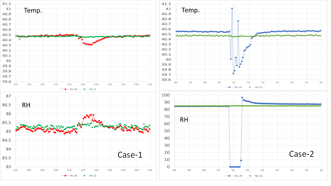
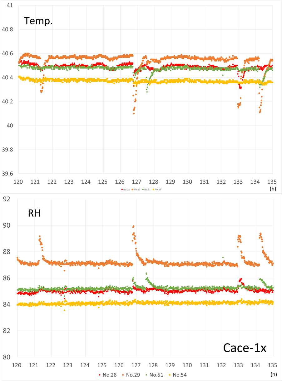
(Case-1)
The phenomenon that temperature and humidity slightly shift is sometimes caused to be in the lower figure.
This phenomenon occurs several times for one hour.As this phenomenon occurs with each sample separately, there is not the cause to a chamber.Do you think that what happens with a sensor?

(Case-2)
For several minutes, humidity became 0%RH, and temperature became unstable.
I can measure other sample without a problem.What should I do to evade such a case?

  • Dear Josh

    This Issue is not a problem of the timing of I2C.
    These phenomena were occasionally occurred though I measured for a long term without a problem.
    And, some similar issue occurs in other examination. Possibly these may not be problems only for IC.
    I do not know what I should confirm how now.I want help based on your experience.
    Please consider again.

    Regards,
    Toshi

  • Toshi - from your CASE 2 %RH capture, this looks like a firmware issue that I documented in the FAQ that I pointed you towards. In my experience with folks writing firmware for this part, the best way to see this is to put a logic analyzer on it and see for yourself what timing you have which makes the device return 0x00 0x00 for the humidity data, because not enough time is given for conversion to be completed. 

    For CASE 1 temp and RH, the capture is zoomed in quite a bit, and the part looks to be within expected range for both temp and %RH - can't tell for sure, since I don't know how many samples that represents. There is some movement here, but again, it looks to be reasonably OK and your chamber may have moved around slightly and the HDC caught it doing that. 

  • Dear Josh

    In Cace-1, I think that the change in the chamber surely becomes the trigger, too.
    But the temperature-humidity is moving a big change like Case-1x than I image.
    As the instructions level of the chamber is approximately constant, I do not think that temperature-humidity is doing a big change.
    I think that I cannot explain it only by being sensitive.
    Why do you think that it is behaved in such ways?

    In Case2, you seem to be regarded as a issue of Conversion, but then I ask a question newly.
    What is the reason why Conversion is delayed?
    I think that the frequency of the internal clock does not greatly change.
    Because a value is not stable, by averaging processing to perform until precision is guaranteed, will conversion be late?
    In this case will Conversion not be over in 1500usec?
    Please tell me if there is the method that can guess the conversion time of every time.

    Regards,
    Toshi

  • Toshi - 

    What is the legend for this graph? (what do No.28, 29, 51 and 54 represent)

    Do you have images of your board and the test setup as well as the schematic and exact code flow (in flow chart form) for both your testing and your firmware? 

    Also, if you have logic analyzer captures, that would be helpful (Saleae preferred, but not required)

  • Dear Josh

    Because No.xx is any sample number, please do not mind it.
    A sample PWB is about 20mm□, and there is a connector.
    I evaluated using arudino with a constant temperature tank (800 liter) at 40℃80%RH.
    Case-1x is the result that evaluated four samples at the same time.
    I show below a brief flowchart. As can be seen, it is repetition of the simple work.
    As data become enormous, I do not use a logic analyzer. However, I think that I2C does not have the problem as the error of Ack does not happen. In other words, the value of the register seems to be correct.

    In addition, the value of the register converting confirmed that there was read before DRDY flag became 1 after measur request.
    Therefore it is not thought about a value of the temperature-humidity becoming 0x0000 as for me.

    Regards,
    Toshi

  • Toshi -

    after looking at your Case 1 graphs, i have come to the conclusion that the parts are picking up variations in your chamber. It makes sense as when temp goes down, %RH goes up. We see this all the time in our own chambers, as it is trying to maintain stable environment at high %RH conditions.  

  • Dear Josh

    In Case-1, you think the relations of the humidity temperature are right.
    However, it is time before returning that I keep in mind.
    It takes around ten minutes to be restored.
    In the same chamber, four samples should have a similar tendency.
    However, four samples are not necessarily the same tendencies.
    How can you explain this?

    In addition, I do not understand origin of Case-2 at all.
    At the time of the real use, this is a problem more.
    Why would humidity show 0% of around ten minutes?
    Other samples give normal level then.
    This phenomenon occurred several times during two weeks.
    The solution to Case-2 is urgent.

    Regards,
    Toshi

  • Toshi - 

    if you have a schematic to share or logic captures, that would probably speed things up a bit. To me this looks like a possible firmware bug, which I know you don't believe at the moment, but if you can catch it with logic analyzer, that would be great. One technique to use here for this kind of hard to recreate issue is to set up GPIO to fire when %RH goes that low, triggering logic analyzer to start capturing. Then you could look at the timing your system/firmware is working with, and share with us to analyze.    

  • Dear Josh

    I am planning the method using GPIO, too.
    But, it takes many time until outbreak of this issue.
    I think that the method that I only wait for is not so good.
    I want to hypothesize this phenomena, and I think that I should confirm it.
    I need your help in thinking about a hypothesis.

    Regards,
    Toshi

  • Toshi - 

    I went back to this post https://e2e.ti.com/support/sensors/f/1023/t/968639

    in here you had some timings - I myself did some studies similar to yours, but I had some different results and what I found matched the datasheet, and makes sense as the values we place in the datasheet are made from a large number of samples, and represent our characterization of the device + some statistically responsible guard band added. I think if you could review your code and double check you have removed the reset and are waiting at least 1270uSec (I use 1300uSec, you had 1000uSec in your working for you, which is great, but the fact that you have issues and you documented that you thought 1000uSec wait time was OK says you should go back and look, then adjust so you wait the correct amount of time. This is exactly the case here that I pointed you to earlier with the FAQ. Waiting long enough for the temp conversion to complete, but not long enough for the %RH conversion to complete is what gives you the zeros.   

  • Dear Josh

    I will adopt your advice and challenge the evaluation in analyzers using GPIO.
    Finally, let me ask you just one more question.

    When a capacitance of the polyimide dielectric is measured, under the influence of the outside, may conversion time become long? (For example, more than 1500usec)
    Or, does the conversion time of the humidity not change regardless of outside influence?
    Which one?

    Regards,
    Toshi

  • Toshi - 

    As shown in the datasheet the typical total time for 14 bit conversions (temp + %RH) is 1270uSec. 

    In the histogram generated during characterization, the typical time for %RH conversion (this takes the longest time) is what is in the datasheet and there was at least one part that went to ~689uSec, and one device that went to 637uSec for the 14 bit temperature conversion, so if you wanted to cover all your bases, you could increase waiting time to 1325uSec (1.325mSec) and probably never run into an issue. Also, you can leverage register 0x04 and the DRDY/INT IRQ line to add double and triple redundancy to your system and avoid any issues related to your waiting time. IRQ will fire when data is ready, 0x04 will set bit 7 to a 1 (yielding a 0x80) at same time, if you check both, then read, I really don't see you running into this issue ever again. 


  • Dear Josh
    Thank you for your discussions. But, the point at issue slips off. I arrange issues again.

    ・In case-2, this is the result that measured temperature-humidity every one minute in waiting time of 3000usec.
     3000usec is more than double of 1325usec.
      I performed the confirmation of the conversion time of HDC2010.(e2e.ti.com/.../968639)
    ・However, this case that humidity became 0 occurred.
      I am analyzing the cause that became 0 suddenly.
    ・I got the following facts about waiting time.
     If waiting time is short in the case of Soft_reset, the data are initial values.(Table3)
     Even if waiting time is short in case of Measurement trigger, humidity is not 0%RH.(Table4)
     And, even if DRDY does not become 1, humidity is not 0%RH.(Table4)

    For the moment, I will adopt your advice and challenge the evaluation in analyzers using GPIO.
    Regards,
    Toshi

  • Toshi, with regards to the time to wait after software reset, i found that >550uSec was about the minimum to wait (at room temp) if issued before initiating further I2C communications, and this should be checked on your side over temperature if you leave it in, and again i recommend to remove it. Going below that leads to negative results as you have seen. 

    If you can have a look at this simple flow, which is just firmware, not using the DRDY/INT pin, this is a very robust approach. 

    and also here is logic shot of the loop above, but with the DRDY/INT also involved to trigger read of the 0x04 register, for best results from what part can offer you in the form of notification that fresh data is indeed available and the IRQ is serviced and reset.  


  • Dear Josh

    The method to watch DRDY which you suggest is effective. However, this method have a big problem in the true use.
    The problem is processing when DRDY does not change to 1.
    If not to be able to leave from the loop is equal to the trouble of the sensor, the mass production is too high-risk.
    I cannot take the measures without investigating the cause or confirmation of the effect of the soft reset.

    Now, I was starting the measurement in environment using GPIO.
    I continued measurement, but the trouble did not occur as three hours. I intend to evaluate after tomorrow.

    And, I confirmed time dependence with some samples, too.
    I measured dependence three times with three samples, but the tendency was the same.
    Each sample were some dispersion, but there was little dispersion of individual samples.

    Regards,
    Toshi

  • Toshi - 

    all your times are way too fast. Please follow my guidance, which matches the datasheet and the way the part is intended to be handled. 

  • Dear Josh

    I say many times. I am measuring at 3 msec after the measurement request every time.

    <control procedure>
    Add 3.3V - - (900 msec) - -> write 0x0e "0x80" - - (8 msec) - -> 0x0f "0x01" - - (3 msec) - -> data read ... wait ...(repeat: 0x0f "0x01"----> data read ... wait ...)

    I only showed ability of HDC2010 to you.

    Though the waiting time is 3msec more than ability, why does Case-2 occur?
    I am asking you for this question.

    Regards,
    Toshi

  • Toshi, your chart in previous says uSec (microseconds), yet you continue to reference 3mSec (milliseconds) - sorry for the confusion, but i can only base advice on what you are providing, to me it seems this way. 

    if you have any logic captures with timing as i have provided to you as examples, this would show us what is actually happening. 

  • Dear Josh

    About the condition of specifications, please explain it to me.
    The electrical characteristic table has a movement range of the humidity.
    There is explanation in the proviso as follows.

    (11) Recommended humidity operating range is 20 to 80% RH (non-condensing) over 0 to 60°C.
    Prolonged operation beyond these ranges may result in a shift of sensor reading, with slow recovery time

    Q1: What is the shift of sensor reading?
    Q2: What is the slow recovery time?
    Please teach me by showing something concretely.

    This issue to become the low humidity has a tendency.
    Low humidity trouble occurs with some machines equipped with the temperature-humidity sensor, but takes place out of a recommended humidity range. (For example, it is 40℃ 85%RH, 25℃ 10% etc.)
    Do you notice any problem?

    In addition, my evaluation is not advancing now without being able to reproduce the trouble.

    Regards,
    Toshi

  • Toshi - 

    sorry for the delay in getting back to you on this. I did receive the collateral from our local guy helping you. 

    Please find attached working Energia code and logic capture which you can use directly or for reference.

    /cfs-file/__key/communityserver-discussions-components-files/1023/6607.HDC2_5F00_address_5F00_40_5F00_one_5F00_shot_5F00_01_5F00_21.txt

    /cfs-file/__key/communityserver-discussions-components-files/1023/HDC2_5F00_one_5F00_shot_5F00_example.logicdata

    Viewer for the Saleae file is here : https://www.saleae.com/downloads2/

    I used both MSP430F5529 and MSP430G2553 – only difference was the UART baud rate

    This code uses I2C address 40 as you are and issues first start conversion in setup, with correct waiting time. 

    After going into loop, second start conversion is at the end, with the waiting time set correctly, but with other lines you can comment in/out as you like to see the behavior

    In here on line 75, I also placed an if statement, which, when waiting time is too short, will not read values out of the device until register 0x04 reads 0x80 (or 128 dec) 

    There are no issues using 3mSec or more, but 1.5mSec is recommended when using 14 bit conversion setting.

    The current loop delay is set on line 99 and is currently set for 1 sec.