This thread has been locked.

If you have a related question, please click the "Ask a related question" button in the top right corner. The newly created question will be automatically linked to this question.

IWR6843: IWR6843 Certification Firmware

Part Number: IWR6843
Other Parts Discussed in Thread: MMWAVEICBOOST, , DCA1000EVM, UNIFLASH

Hi,

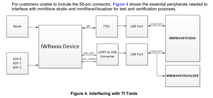
I'm getting ready to go through the certification process with an IRW6843 based product and an looking for a way of generating the test frequencies without going through mmWave studio. I cannot easily connect my product up to a DCA1000 or mmWaveICBOOST carrier board as the instructions state. I also don't have easy access to IWR6843 SPI interface (I have only implemented UART).

I have seen that the required firmware for certification can be combined into a meta image (e2e.ti.com/.../3261973 which is useful, but still does not provide a way of running the required commands over UART.

Ideally I'd like to be able to build a custom version of mmwave_studio_02_00_00_02\rf_eval_firmware\masterss\xwr68xx_masterss.bin which I can control using UART. Is there any chance the source code of mmwave_studio_02_00_00_02\rf_eval_firmware\masterss\xwr68xx_masterss.bin could be made available?

Alternatively, as the only requirement for this firmware is to generate continuous waves at 60, 62, and 64GHz would it be possible to get a metaimage (or several meta images) which only have this function?

This is related to this question where the poster has a similar issue: e2e.ti.com/.../887815

  • Hi,

    As you see from the referenced post, SPI is needed  and currently CW is only supported on mmwavestudio.

    What certification are you trying to do? There may be a workaround besides generating CW waves?

    Regards,

    Charles O

  • Hi,

    We have custom hardware and have connected up SPI to the IWR6843 but our hardware is getting stuck on the mmWave Studio SPI Connect step (5).

    I have a few questions:

    Document SPRACP3A figure 4 specifies that only SPI CFG Uart and MSS_Logger is required. See diagram below.

    I have two questions:

    1) Exactly what SPI pins are required to be connected I have connected, MISO, MOSI, CLK, CS. Or are other connections required to go the FTDI ic? I have these SPI pins connected and SPI data is flowing but I still get the following error when clicking "SPI Connect (5)" button:

    [16:26:56] [RadarAPI]: ar1.PowerOn(0, 1000, 0, 0)
    [16:26:56] Status: Failed, Error Type: RESP TIMEOUT
    [16:27:00] MSS Power Up async event was not received!

    2) Is the Radar-mss_logger pin required to be connected - I can not see any option for where this connects to this com port in mmwave studio?

  • Hi,

    Are you using the same FTDI on the MMWAVEICBOOST?  

    The Radar-mss_logger is not needed to interface with mmWaveStudio.

    Regards,

    Charles O 

  • Hi Charles,

    I have copied the EEPROM from the MMwaveICboost FT4232H to the DS_FT4232H_Mini_Module and wired to the same pins as the dev kit is using. MMwave Studio detects and communicates with the DS_FT4232H development board Ie SPI coms is outgoing and data is coming back but still errors. See below for wiring. 

    Are there any other SPI pins required to be connected?

    Cheers,

    Matt

  • Hi,

    1. Can you share a screen shot of the studio interface ?
    2. Looking at the DCA1000EVM header the reset and host_INT is also routed, can you confirm you have this routed also?

    Regards,

    Charles O

  • Hi Charles,

    1 - See below

    2a- I have now connected host_INT which allow the SPI coms to get further. But still seems to be getting stuck - see above. There is definitely SPI communication occurring with what looks like valid data going on MOSI and MISO.  I can provide this if it would help diagnose the problem?


    2b -Reset. I have put a logic analyser on the reset pin and this is only asserted on "Set (1)" command, I have asserted this internally in the MCU on startup which should be that same.

    Thanks,

    Matt

  • Matt,

    Sometimes the RF power on fails because there is a program on the SFLASH. Can you erase the SFLASH using UNIFLASH and try it again?

    Regards,

    Charles O

  • Hi Charles,

    I have cleared the flash using uniflash and no difference.

    I also made sure the reset was low for 500ms the same as the "set (1)" output does.

    Is there any C libraries for the SPI coms that I could use to port directly to the host MCU on my board to allow to put in the CW modes?

    What about specific bin file that would put the chip in the CW mode on programming?

    Any other ideas? We require this for certification testing and this is really pushing out our timelines.

    Cheers,

    Matt

  • Hi Matt,

    is this for frequency stability test? There is way to do that without needing CW

    Can you wire these pins to the MMWAVEICBOOST and use that instead? May be a faster approach at this point.

    Regards,

    Charles O

  • Hi Charles,

    We are looking to certify against these key FCC standards:
    Radiated Emissions FCC 15.209 and 15.109
    Band Edge Measurement FCC Part 15.209
    60, 120 GHz fundamental and harmonics measurement of radar FCC Part 15.255 (B)(2)
    Verification of antenna FCC Part 15.203

    Our test certifier has asked for firmware for continuously transmitting on the lowest, highest and one channel in the middle and also normal production FW mode.

    Would it be possible to have an offline conversation about this? If so can you contact Matt and I directly via a private message to organise a time.

  • Hi,

    I sent you a request, can you accept it so I can send you direct messages?

    Regards,

    Charles O