This thread has been locked.

If you have a related question, please click the "Ask a related question" button in the top right corner. The newly created question will be automatically linked to this question.

PGA460-Q1: About digital raw data in PGA460-Q1

Part Number: PGA460-Q1
Other Parts Discussed in Thread: MSP-EXP430F5529LP, BOOSTXL-PGA460, , PGA460, MSP430F5438A, ENERGIA, MSP430F5529

Hi, team

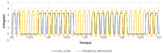
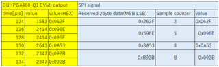
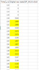
I measured digital raw data from PGA460-Q1(BOOSTXL-PGA460) using MSP-EXP430F5529LP and PGA460-Q1 EVM.
(PGA460-Q1 Datasheet p47-48)
However, I confrimed the same value in a row about ADC data(DP_MUX=0x4).
The same thing happened in BPF data(DP_MUX=0x3), Rectfiler data(DP_MUX=0x2) and Peal Hold and LPF data(DP_MUX=0x1);

Sampling cycle is 2μs/sample(SAMPLE_SEL=1).


Are these digital waw data normal?
Why did this thing happen?

regards,

  • Hi Tr, 

    Can you tell me what SPI speed you are using?  If your SPI speed is slightly below or above 8 MHz, you may miss samples or get a few extra samples, as is described in the below post:

    https://e2e.ti.com/support/sensors/f/sensors-forum/897329/pga460-q1-is-there-any-buffering-of-the-direct-data-burst?tisearch=e2e-sitesearch&keymatch=pga460%252520direct%252520data%252520burst 

    Thank you,

    Mekre

  • Hi Mekre,

    Thank you for your reply.

    I measured them using GUI(PGA460-Q1 EVM).

    Where can I comfirm SPI speed?

    Thank you,

  • Hi Tr,

    I am referring to the frequency of the SPI clock that is output from the microcontroller.  You should be able to get this info by proving the SPI clock pin on the microcontroller or the PGA460.  

    Regards,

    Mekre

  • Hi Mekre,

    I measured the voltages of SPI clock and 8-MHz clock test pin(TEST_MUX VALUE = 0x05).

    As I see, SPI speed(BLUE line) was 8 MHz.

    However, the logic high/low timing of SPI clock and 8-MHz clock of PGA460 didn't match.

    Can this be the problem?

    Regards,

  • Hi tr,

    If the timing of the SPI clock edges was consistent and the frequency matches the device frequency, this may not be an issue after the first sample.  When I look at your graph, I noticed that there is a gap between some of the SPI clocks though.  Since the direct data burst data is not buffered (https://e2e.ti.com/support/sensors/f/sensors-forum/897329/pga460-q1-is-there-any-buffering-of-the-direct-data-burst ), it is possible that you may lose samples.  To verify if this is an issue, you can set SAMPLE_SEL to 1.  By setting SAMPLE_SEL to 1, the MS Byte is padded with a 4 bit sample counter.  After doing this, check the sample counter to see if it is being properly increment between samples.

    Regards,

    Mekre

  • Hi Mekre,

     The sample counter seems to increase by 3.

    I compared the values obtained from PGA460-Q1 EVM (yellow) and the values from SPI logistic signal(blue) using the oscilloscope. 

    Apparently, the phenomenon that the same value continues was due to GUI.

    The lost  sample counter 4, 6  was replaced by the sample counter 5 in GUI output.

    To get digital raw data using  PGA460-Q1 EVM, is there any setting required?

    Regards,

  • Hi Tr,

    You seem to be missing samples.  I would expect the sample count to increment by 2 instead of 3, similar to the below thread:

    https://e2e.ti.com/support/sensors/f/sensors-forum/951295/pga460-direct-data-burst---byte-count-varies?tisearch=e2e-sitesearch&keymatch=pga460%20direct%20data%20burst#

    Was your previous clock frequency scope trace generated when using the GUI?

    Regards,

    Mekre

  • Hi Mekre,

    >Was your previous clock frequency scope trace generated when using the GUI?

    Yes. I measured the voltages of SPI clock when using the GUI.

    Regards,

  • Hi tr,

    The gap in the clock seems to happen after 8 clock cycles from your graph.  This may be from the delay in reloading the SPI TX buffer between the dummy writes used to active the clock.  If you were to decrease the delay between the dummy writes by using the DMA of your microcontroller, that should help reduce the number of skipped samples.  You may still  skip samples though if your clock is slow.  To deal with the skipped samples, you could try to use the previous sample value for a given data point that was skipped in post-processing of the collected data, as is mentioned in the below post:

    e2e.ti.com/.../pga460-q1-is-there-any-buffering-of-the-direct-data-burst

    Regards,

    Mekre

  • Hi Mekre,

    How can I turn MSP-EXP430F5529LP into the DMA mode.

    Can I set it using the GUI?

    Thanks.

  • Hi Tr,

    This is something that is not supported by the GUI or Energia code.  To implement this feature, you will have to write custom code.  For this custom code, you can use one of the MSP430F5438A DMA code examples as a starting point.  

    Regards,

    Mekre

  • Hi Mekre,

    Thank you for your help.

    However, I cannot get rid of the gap in the clock.

    Probably, the code  is not written accurately to put it in DMA mode.

    Is there wrong in the following code about initial setting?

    // DMA setup
    UCB1CTL1 |= UCSWRST; // **Put state machine in reset**
    UCB1CTL0 = UCMST+UCSYNC+UCCKPL+UCMSB; // 3-pin, 8-bit SPI master
    // Clock polarity high, MSB
    UCB1CTL1 = UCSSEL_2; // SMCLK
    UCB1BR0 = 0x02; // /2
    UCB1BR1 = 0x00; //
    UCB1MCTL = 0x00; // No modulation
    UCB1CTL1 &= ~UCSWRST; // **Initialize USCI state machine**

    DMACTL0 = DMA1TSEL_22; // DMA0 - UCB1TXIFG
    // Setup DMA0
    DMA0DA = (uintptr_t) &UCB1TXBUF);
    // Destination single address
    DMA0SZ = 1; // Block size
    DMA0CTL = DMASRCINCR_3+DMASBDB+DMALEVEL; // inc src
    DMA0CTL |= DMAEN; // DMA0 Enable

    Also, what code is required after sending the BURST_LISTEN command?

    Regards,

  • Hi tr,

    After you initialize the test_mux register and then perform a burst and listen command, you would then need to output the SPI clock so that the PGA460 can send out the data stream.   

    If you are having issues with using the DMA for outputting the clock, do you see a gap in the clock if you write to the TX buffer and then loop until the buffer is ready for the next character?  You can do this with the operations shown in red below:

    while (!(UCB1IFG & UCTXIFG));
    UCB1TXBUF = 0xFF;
    while (!(UCB1IFG & UCTXIFG));
    UCB1TXBUF = 0xFF;
    while (!(UCB1IFG & UCTXIFG));

    Regards,

    Mekre

  • Hi Mekre,

    Thanks to your code, the gap has been shortened a lot, however, it hasn't disappeared completely yet (There is a gap of about 1 clock for every 4 bytes).

    Probably,  DMA setup is not seem to be running correctly.


    By the way, I have a trouble about MSP430F5529.

    (I should create a new thread, but I don't access the ''Ask a new question' forum.)

    When I increase the SPI clock from 6.25MHz(UCB1BR0 = 0x04) to 8.333MHz(UCB1BR0 = 0x03), I confirmed symptoms of incorrect communication. MSP430F5529 does not receive the correct byte at 8.333MHz.

    For example,

    ( 6.25MHz)  → ( set 8.333MHz

    0x60   →   0xC1

    0x80   →   0x00

    I checked the correct CLK and MISO signal was sent from PGA460 using an oscilloscope.

    I think the clock is out of sync with MISO logic ,and a data may be sampled on the leading edge of the clock.

    Could tell me to get the correct communication at 8MHz?

    Thank you always for your support.

    regards.

  • Hi Tr,

    Do you see the following bar and the button circled in blue at the top of your browser:

    Can you try setting the clock closer to 8 MHz instead of 8.33 MHz? 

    Also, what commands are you using to read the SPI RX buffer?

    Regards,

    Mekre

  • > Do you see the following bar and the button circled in blue at the top of your browser:

    I confirmed that it can be opened normally.Thanks.

    >Can you try setting the clock closer to 8 MHz instead of 8.33 MHz? 

    I'm ashamed not to know how to run at closer 8MHz.

    Could tell me the way to set just 8MHz?

    >what commands are you using to read the SPI RX buffer?

    I am using the following command.

    for(i=0; i<Data_size ;i++){

    while (!(UCB1IFG & UCTXIFG));
    UCB1TXBUF = 0xFF;

    Data[i] = UCB1RXBUF;

    }

    Are there something wrong?

    Regards,

  • Hi Tr,

    Try the following code instead to see if you are able to properly read the data from the PGA460:

    for(i=0; i<Data_size ;i++){

    while (!(UCB1IFG & UCTXIFG));
    UCB1TXBUF = 0xFF;

    while (!(UCB1IFG & UCRXIFG));
    Data[i] = UCB1RXBUF;

    }

    Regards,

    Mekre

  • Hi Mekre,

    Thank you.

    I am going to try it.

    However, the problem incorrect communication has not been resolved yet.

    Can MSP-EXP430F5529LP communicate at closer 8MHz clock?

    This symptoms happen regardless of DMA mode.


    regards,

  • Hi tr,

    Could you start a new thread about your clock questions?  Also, please let me know if adding the UCRXIFG line I mentioned above solves the issue you had for properly reading the value sent by the PGA460.

    Thank you,

    Mekre