This thread has been locked.

If you have a related question, please click the "Ask a related question" button in the top right corner. The newly created question will be automatically linked to this question.

IWR6843AOP: Integration of the device into our application and product

Part Number: IWR6843AOP

Hi,

Based on the previous suggestions I have tested the .cfg file on the long range demo by making some changes in the parameters of the function that were mentioned earlier.

sensorStop
flushCfg
dfeDataOutputMode 1
channelCfg 15 7 0
adcCfg 2 1
adcbufCfg -1 0 1 1 1
profileCfg 0 60 35 6 43.0 394758 0 8.241 1 125 3433 0 0 48
chirpCfg 0 0 0 0 0 0 0 1
chirpCfg 1 1 0 0 0 0 0 4
frameCfg 0 1 128 0 100 1 0
lowPower 0 0
guiMonitor -1 1 0 0 0 0 0
cfarCfg -1 0 2 8 4 3 0 10 0
cfarCfg -1 1 0 4 2 3 1 10 0
multiObjBeamForming -1 1 1
clutterRemoval -1 1
calibDcRangeSig -1 0 -5 8 256
extendedMaxVelocity -1 0
bpmCfg -1 0 0 1
lvdsStreamCfg -1 0 0 0
compRangeBiasAndRxChanPhase 0.0 1 0 1 0 1 0 1 0 1 0 1 0 1 0 1 0 1 0 1 0 1 0 1 0
measureRangeBiasAndRxChanPhase 0 1.5 0.2
CQRxSatMonitor 0 3 4 63 0
CQSigImgMonitor 0 127 4
analogMonitor 0 0
aoaFovCfg -1 -90 90 -90 90
cfarFovCfg -1 0 0 159.0
cfarFovCfg -1 1 -80 80
%SceneryParam -50 50 0.5 60 -6 6
staticBoundaryBox -50 50 0.5 60 -6 6
boundaryBox -50 50 0.5 60 -6 6
gatingParam 4 6 6 6 10
stateParam 4 10 60 600 20 600
allocationParam 30 30 0.5 3 2 2
maxAcceleration 0.1 0.1 0.1
trackingCfg 1 2 250 20 78 121 99
sensorPosition 2 0 0
presenceBoundaryBox -3 3 2 6 0.5 2.5
sensorStart

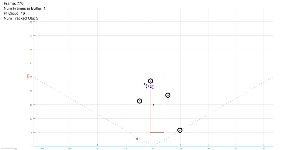
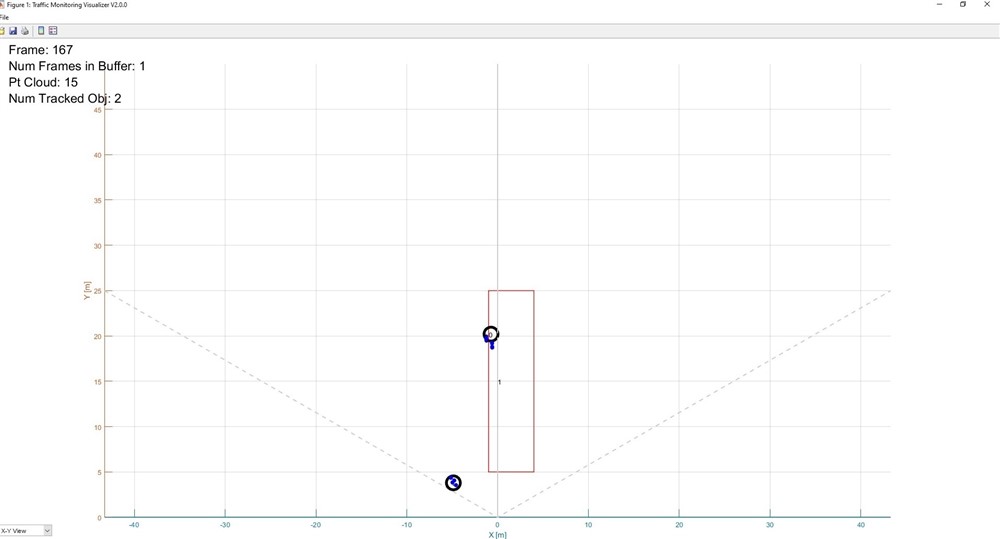
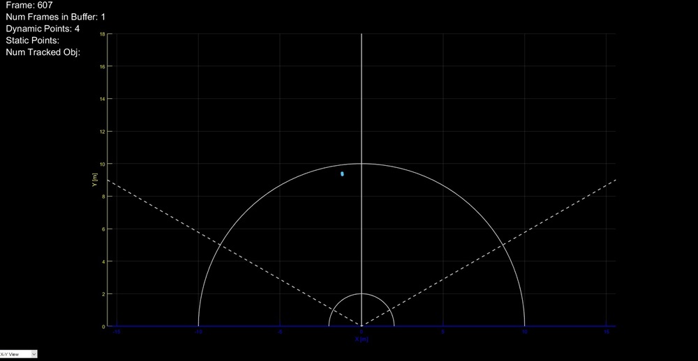
I tired running .cfg by change one parameter at a time and that didn't make much difference. Making both the changes on the functions it got little better but I still see some changes that are need to be made. Also I do not see an impact of changing the Fov in aoaFovCfg. The targeted points on the long range that are passing by somehow leaving the trace and you see it as a point for a while and then either disappears or stays. What could be the possible highest threshold for cfarFovCfg. What could be the possible reason for the delay ? Now I would be testing the same with area scanner.

Regards,

Divya


  • Hello

    Can you please take a look at the latest documents released as part of the  Industrial tool boxk 4.7.x to see additional guidance  on tuning the demos.

    Thank you,

    Vaibhav

  • Hi Vaibhav,

    Thank you for the reply. This is a related question to the closed ticket. Could you please link it to it? 

    (+) IWR6843AOP: Integration of the device into our application and product - Sensors forum - Sensors - TI E2E support forums

    Regards,

    Divya Teja Settimali

  • Hello Divya,

    I have gone through the previous chat, but maybe it would be good to list the specific performance issue you are seeing at this time?

    The SDK user guide will have limits for any of the CFG commands that have limits. There aren't practical limits on the cfarFOV commands, so any reasonable value should be ok. Have you looked at the data output of the sensor to see what the pointcloud SNR, velocity, and other parameters is? This will help you determine what the thresholds should be to filter out some unwanted points. 

    Regards,

    Jackson

  • Hi Jason,

    Thank you for the information. I used sensing estimator to figure out the chirp parameters. Could you please answer the following questions:

    1. The area scanner can detect a target upto 8 meters to be precise and after that the sensor just detects them as multiple dynamic points So can we increase the range upto 20 meters and detect the targets upto 20 meters?

    2. The long range can detect the target perfectly upto 20 meters and later on somehow starts seeing as dynamic points. When it comes to long range it starts seeing multiple ghost points as targets. I did try to reduce the transmit power, increase the detection threshold (I increased these values gradually in the .cfg file to see if the situation is improving but didn't help much) and there was no clutter in the scene.

    Please provide a solution to either delete all the ghost points in the long range demo or increase the range value of the area scanner.

    Regards,

    Divya Teja Settimali

  • Hello Divya,

    The area scanner lab should be fairly simple to increase the range. If you are using the default cfg file provided with the lab, perform the two below modifications.

    Reduce the chirp slope to increase the maximum range of the detection. You can see documentation for this command in the SDK user's guide.

    profileCfg 0 60.5 100 25 69 0 0 40 1 256 6000 0 0 30

    Increase the maximum number of range bins looked at by the static detection chain. There is more info on the static detection parameters at the below document.

    heatmapGenCfg -1 1  0 6 150 60.0 3.0 10
    "C:\ti\mmwave_industrial_toolbox_4_7_0\labs\area_scanner\68xx_area_scanner\chirp_configs\cli_commands.pdf"

    For the long range detection, are you saying it will track the person well but once they get farther than 20m it starts creating ghost tracks? Or do they appear after configuring the demo to create tracks farther than 20m? Is it a change in cfg file that causes this issue or just dependent on where people are located?

    Regards,

    Jackson

  • Hi Jason,

    1. To increase the range of area scanner demo when I uploaded the .cfg values in the original file with 

    profileCfg 0 60.5 100 25 69 0 0 40 1 256 6000 0 0 30

    heatmapGenCfg -1 1  0 6 150 60.0 3.0 10

    as suggested there was a warning on the screen and data was never plotted.

    Below is the warning:

    Warning: A timeout occurred before the Terminator was reached.

    'serial' unable to read all requested data. For more information on possible reasons, see <a href="matlab: helpview(fullfile(docroot, 'instrument','insrument.map'), 'serial_somedata')" '> Serial Read Warnings </a>

    Same happened when I tired the values from the mmwave sensing estimator. It either gives this message or says error -1.

    I took the values from the sensing estimator and changed as follows

    sensorStop
    flushCfg
    dfeDataOutputMode 1
    channelCfg 15 7 0
    adcCfg 2 1
    adcbufCfg -1 0 1 1 1
    profileCfg 0 60.5 7 6.4 2025 0 0 1.49 1 6053 3000 0 0 30
    chirpCfg 0 0 0 0 0 0 0 1
    chirpCfg 1 1 0 0 0 0 0 2
    chirpCfg 2 2 0 0 0 0 0 4
    frameCfg 0 0 1 0 6.096 1 0
    lowPower 0 0
    guiMonitor -1 1 0 0 0 0 0
    cfarCfg -1 0 2 8 4 3 0 20 0
    cfarCfg -1 1 0 4 2 3 1 15 0
    multiObjBeamForming -1 1 0.5
    clutterRemoval -1 1
    calibDcRangeSig -1 0 -5 8 256
    extendedMaxVelocity -1 0
    bpmCfg -1 0 0 1
    lvdsStreamCfg -1 0 0 0
    compRangeBiasAndRxChanPhase 0.0 1 0 -1 0 1 0 -1 0 1 0 -1 0 1 0 -1 0 1 0 -1 0 1 0 -1 0
    measureRangeBiasAndRxChanPhase 0 1.5 0.2
    CQRxSatMonitor 0 3 15 125 0
    CQSigImgMonitor 0 115 6
    analogMonitor 0 0
    aoaFovCfg -1 -90 90 -90 90
    cfarFovCfg -1 0 0 11.11
    cfarFovCfg -1 1 -2.04 2.04

    % *****************TRACKING COMMANDS*****************************
    staticBoundaryBox -8 8 0 8 -1 2
    boundaryBox -8 8 0 8 -1 2
    gatingParam 4 2 2 2 10
    stateParam 20 10 10 50 1
    allocationParam 200 155 0.5 10 2 2
    maxAcceleration 0.1 0.1 0.1
    trackingCfg 1 2 250 20 20 260 100 90

    % *****************STATIC DETECTION COMMANDS*********************
    heatmapGenCfg -1 1 0 6 50 60.0 3.0 10
    staticDetectionCfg -1 0 -50.0 +50.0 -30.0 20.0 0.7 5.0 0.2 4 20.0

    So how do I proceed further?

    2. In Long range the .cfg files that are available on the demo are generating the ghost points with both 2D and 3D .cfg files.

    If you see the below screenshots

    This is a screenshot from the 2D .cfg file. Only 1 is the actual target and it is creating multiple ghost points as the target is coming closer to the sensor.


    This is a screenshot from the 3D .cfg file. Only 0 is the actual target and it is creating multiple ghost points as the target is coming closer to the sensor but it is still better than the 2D.

    Now how do I get rid of these ghost points?

    Regards,

    Divya Teja Settimali

  • Hello Divya,

    I forgot you are using the AOP EVM. To use the AOP device with longer range area scanner, you must configure a region of less than 60 range bins.

    heatmapGenCfg -1 1  0 90 150 60.0 3.0 10

    The bold values give the reported range bins for static object detection. From the cfg file (area scanner default) each range bin is ~8cm. So this can be configured for any ~5m range. The above configures the sensor for about 7m (90*8cm) to 12m(150*8cm). These values can change depending on your range needs. To configure for 20m range, you could use 190 and 250 as the range bins, but you might be at the edge of what the AOP antenna can detect. Please make sure the chirp configuration can also support >20m maximum range (may require a chirp slope/BW change)

    And for the long range demo, have you tried adjusting the allocation and state parameters? This is the best way to modify the tracker allocation. Please see the customization guide below. (Note: the long range demo uses a slightly older implementation, but the adjustments should be the same)

    3D_people_counting_tracker_layer_tuning_guide.pdf

    Regards,

    Jackson

  • Hi Jason,

    Adjusting the allocation parameters and state parameters definitely helped us to get rid of the ghost points. Thank you for the help there.

    In the area scanner I changed the parameters in the below function as suggested:

    heatmapGenCfg -1 1  0 90 150 60.0 3.0 10 but there is no change in the detection range after 8 meters it just turns into dynamic points as shown in the below picture.


    and 

    heatmapGenCfg -1 1  0 190 150 60.0 3.0 10 but it is the same message that's been flashed.

    Warning: A timeout occurred before the Terminator was reached.

    'serial' unable to read all requested data. For more information on possible reasons, see <a href="matlab: helpview(fullfile(docroot, 'instrument','insrument.map'), 'serial_somedata')" '> Serial Read Warnings </a>


    How to solve this in the area scanner?

    Regards,

    Divya Teja Settimali

  • Hi Divya,

    For the first config line, 8m seems accurate. The range bin range [90 150] will cover about 7-11m from the sensor for static detection. But remember this is from the sensor and since the sensor is likely up in the air, 11m on the ground will be greater than 11m from the sensor.

    For the second line, you have the numbers reversed. The first number is min range bin and the second is max, so you should swap them as below.

    heatmapGenCfg -1 1  0 150 190 60.0 3.0 10, or did you mean to use 190 and 250?

    Regards,

    Jackson

  • Hi Jason,

    I will check with the area scanner again and come back to you. I got a new issue with the long range that is If the target is starting from the sensor to a far away distance the ghost points aren't a problem and it follows the target upto 25+ meters. But when a target comes into the scene at 25 meters it doesn't see it as a target so it follows the dynamic points and when it comes close at about 10 to 11 meters it is deducted as a target. I want a solution where the ghost points are not appearing and it deducts target at any point in between 20 meters.

    The following is the .cfg file I have used for the long range:

    sensorStop
    flushCfg
    dfeDataOutputMode 1
    channelCfg 15 7 0
    adcCfg 2 1
    adcbufCfg -1 0 1 1 1
    profileCfg 0 60 35 6 43.0 0 0 8.241 1 125 3433 0 0 48
    chirpCfg 0 0 0 0 0 0 0 1
    chirpCfg 1 1 0 0 0 0 0 4
    chirpCfg 2 2 0 0 0 0 0 2
    frameCfg 0 2 96 0 100 1 0
    lowPower 0 0
    guiMonitor -1 1 0 0 0 0 0
    cfarCfg -1 0 2 8 4 3 0 10 0
    cfarCfg -1 1 0 4 2 3 1 10 0
    multiObjBeamForming -1 1 0.5
    clutterRemoval -1 1
    calibDcRangeSig -1 0 -5 8 256
    extendedMaxVelocity -1 0
    bpmCfg -1 0 0 1
    lvdsStreamCfg -1 0 0 0
    compRangeBiasAndRxChanPhase 0.0 1 0 1 0 1 0 1 0 1 0 1 0 1 0 1 0 1 0 1 0 1 0 1 0
    measureRangeBiasAndRxChanPhase 0 1.5 0.2
    CQRxSatMonitor 0 3 4 63 0
    CQSigImgMonitor 0 127 4
    analogMonitor 0 0
    aoaFovCfg -1 -90 90 -90 90
    cfarFovCfg -1 0 0 59.99
    cfarFovCfg -1 1 -40 40.00
    staticBoundaryBox -50 50 0.5 60 -6 6
    boundaryBox -50 50 0.5 60 -6 6
    sensorPosition 2 0 0
    gatingParam 4 6 6 6 10
    stateParam 3 2 2 500 5 60
    allocationParam 40 100 0.1 20 2 1
    maxAcceleration 0.1 0.1 0.1
    trackingCfg 1 2 250 20 78 121 99
    presenceBoundaryBox -3 3 2 6 0.5 2.5
    sensorStart

    Regards,

    Divya Teja Settimali

  • Hi Divya,

    This also sounds like it requires a change to the allocation parameters. Please see again the documentation for these above. Probably you will need to reduce the SNR threshold, or reduce the number or points required. 

    Regards,

    Jackson