This thread has been locked.

If you have a related question, please click the "Ask a related question" button in the top right corner. The newly created question will be automatically linked to this question.

LMP91200: pH electrode

Part Number: LMP91200
Other Parts Discussed in Thread: LMP7721, ADS1115

Hi,

I am looking into building a pH meter. I see that i have two option

1. go with LMP91200

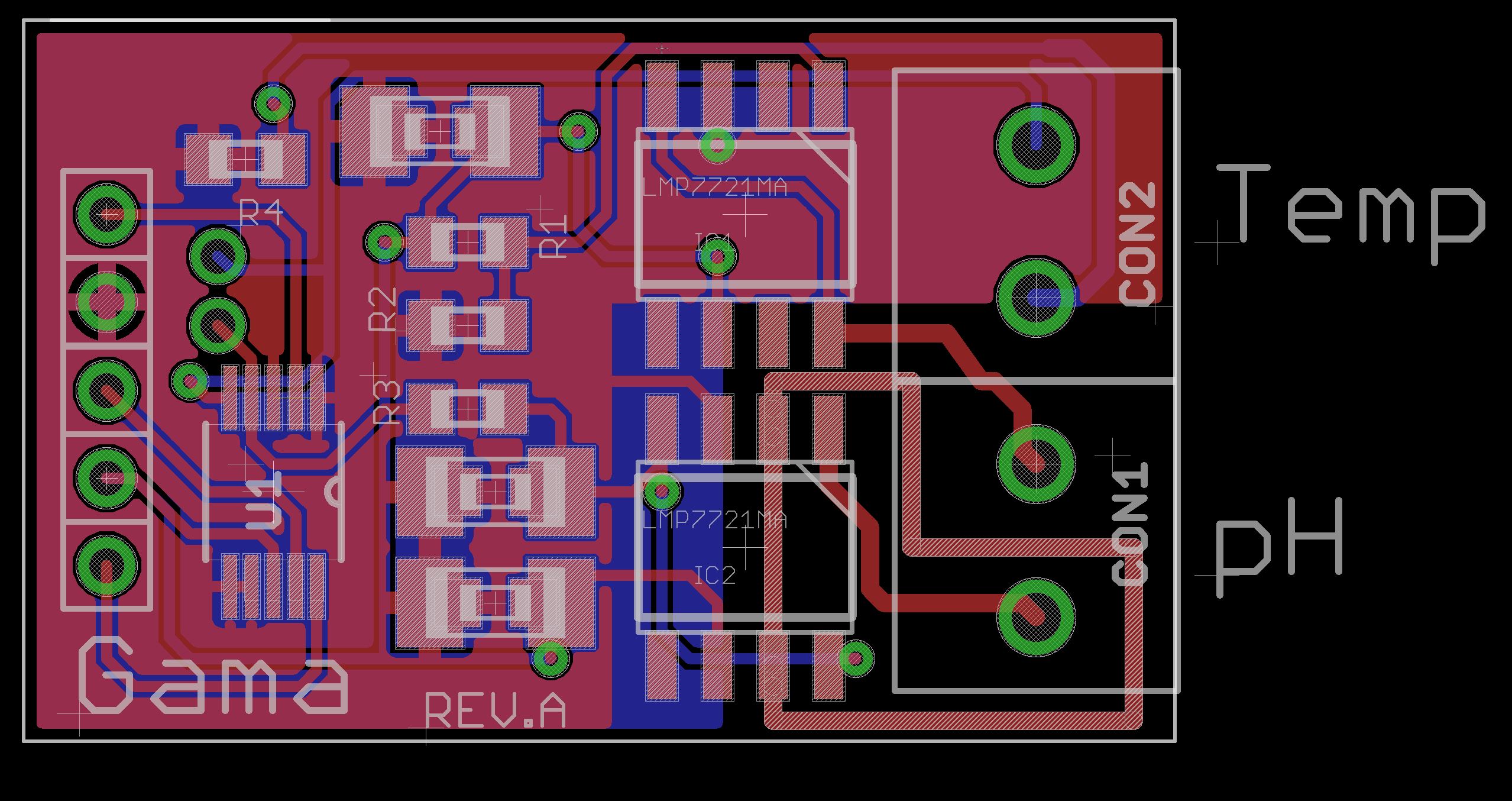
2. build opamp based ph reader using LMP7721

https://www.ti.com/lit/an/snoa529a/snoa529a.pdf?ts=1591757656111&ref_url=https://www.ti.com/product/LMP7721

Question -- For industrial Application which one is a better option. We need reliability and most possible accurate results. 

TI recommends two LMP7721 but can we use just one LMP7721 to read pH electrode.

Thanks

  • Gama,

      Yes you can use two LMP7721 operational amplifiers. You can't use just one. The PH probe is operating as a current sensor and needs a transimpedance amplifier with a common mode voltage with a zero reference. The problem with the LMP7721 is that you have to create this in your design. There is plenty of documentation on this and the data sheet is a good place to start.

    The LMP91200 has already been designed to do everything you need the transimpedance amplifier to do. It has been used many times in many designs and is considered to be the standard for PH probes. The overall design will be easier with this part. The LMP91200 will give you a smaller PCB footprint.

    Both will work great for your application.

  • Thanks for the quick response.

    We are planning to follow this application note

    https://www.ti.com/lit/an/snoa529a/snoa529a.pdf?ts=1591824695682&ref_url=https://www.google.com/

    While going through the forum looks like a lot of folks have issue getting stable readings using this design. Apart from layout consideration is there anything else we need to keep in mid while designing the board.

    Is there any other op-amp you would recommend for pH reading if we want to keep the footprint of the board extremely small. give that the LMP7721 is quite large.

    Cheers!!!!

  • Gama,

    The LMP91 family of parts have the ability to sense fA (femto Amps) of current. The guard ring is at the same potential as the input but has a much lower impedance to protect the PH sensor node from leakage currents. A solder mask has a fairly low dielectric capacitance, and High Impedance, however it’s not perfect. Having a solder mask over a trace that is as sensitive as the PH node with a guard ring will guarantee that you will have a controller leakage current. The leakage due to the solder mask will change with humidity. This will make your measurements off to start with and you will not know by how much based on the weather.


    Use a proper guard ring and do not cover it with solder mask. Also make sure that the PCB has been properly cleaned and has as low of a ionic contamination as possible. This usually requires water soluble fluxes and hot de-ionized water rinses. (Remember to bake the boards dry after the ionic wash cycle, before powering up the boards) Ionic contamination is from the mineral content in water, and will leave a conductive film on the PCB. Most of the time the ionic conduction is so low that it has no impact on most circuits. In sensor technology the ionic conduction is a big deal.


    Gold plate the copper in the unmasked areas. Gold is the only metal that does not corrode. Anything less will oxidize over time and will become a leakage problem.


    I am not aware of alternate parts that meet the minimum criteria. Input leakage current has to be extremely low, low noise, high bandwidth. Personally I like the LMP91 family. I am sure their are others, but I don't know off the top of my head.


    Most engineers that have problems with PH designs,  have a layout issue. Don't underestimate this. Femto Amps will be sensitive to humidity and temperature. Cleanliness will kill your measurement right out of the gate.

  • Thanks for the detailed info. Yes, i did read about the cleaning process and now i understand that its quite important for the famto Amp. 

    Attaching a screenshot of my layout. I only have the ground plane on my digital ADC side ( ADS1115 for reading Amp output). I did put a Guard rail around Both Amp. Due to limited space i dont think i am doing it in most accurate way.

    (for sch i am following the exact TI recommended sch https://www.ti.com/lit/an/snoa529a/snoa529a.pdf?ts=1591757656111&ref_url=https://www.ti.com/product/LMP7721 . 

    My layout looks like this

    let me know if you see any errors in the layout. 

    In my design i have a 10K thermistor as well. 

    I see in some forum posts TI recommends to add 100 ohm to 1K ohm resistance between Probe +ve and Op-amp ?

    is it required ?

    Thanks

  • Gama,

      The guard ring should be only be one single trace that wraps around the PH probe INP of the PH buffer amplifier. Nothing else should be inside of the guard ring.

    You have the guard rind around the INP pin and a separate floating copper trace around the VCM pin. Remove this floating trace, as the guard ring will do what needs to be done. Floating copper only causes problems and closes the gap between the VCM pin and the guard ring.

    The 100 ohm resistor allows for fine tuning the 1k. It can be tweaked to get a tighter value to hold better accuracies. Your call.

    I would extend the ground plane to just under the IC pins for the guard ring on the bottom layer only and all the way under IC1. This will act as a natural capacitance in the PCB to help keep noise out of the circuit.

  • HI Gordon,

    I updated the ground plane and Guard Ring.

    If i add a 100 Ohm resister between Probe +ve( INP) and Op-Amp input that will have to be inside the Guard ring ?

    In this Evaluation board TI does seem to put some part inside the Guard ring. In all other TI deigns i didnt see any parts inside the guard ring as you said.

    https://www.ti.com/lit/ug/snou004/snou004.pdf?ts=1591888235530&ref_url=https%253A%252F%252Fwww.ti.com%252Fproduct%252FLMP7721

    With 100Ohm the layout will look like this 

    Thanks

  • Gama,

      The INP pin is very high impedance. So yes the 100 Ohm resistor will have to be inside of the guard ring. Both layouts look good.

  • Hi Gordon,

    I can read the pH reliably bit can seem to find any info on temp compensation. 

    do you happen to know If there is any formula can be used to adjusted pH value wrt to temp ?

    Thanks

  • Gama,

    It would be best if the manufacture of the sensor would provide this information in the datasheet in the form of a logarithmic response functions from which you can derive an algorithm, but it doesn't. A common use of gas sensors is in an alarm situation where the designer just needs to know when the sensor reaches a predetermined PPM level. Therefore it's pretty easy to characterize the sensor output by exposing the sensor to that PPM level repeatedly and measuring the output.

    Converting the sensor output to PPM is a bit more complicated and requires a firm understanding of the response characteristics of the sensor and almost always will require a calibration. In most cases the manufacturer's datasheets for these kind of sensors do not provide enough information. Simply you will need to characterize the sensor response by exposing the sensor to known quantities of gas, measure the output voltage , determine the resistance and run a regression analysis to determine the function. Two sensors from the same manufacturer can have very different responses to the same concentration. Different pulse widths, heater voltages and load resistors can affect the output as well. The precision of the passives components used are also important. The sensors will require temperature and relative humidity compensation to adequately convert the output to PPM.

    To convert the sensor output to PPM you need to characterize the transducer by exposing it to known PPM levels of the gas, measure the output of the sensor at each concentration and develop a best fit algorithm. You need to be aware of how long does it take for the sensor to respond to each level of gas. How many reference levels you choose is dependent upon your requirements. You need to repeat this process multiple times to ensure repeatability and to develop a known reference margin. Don't forget to measure the temperature and relative humidity response characteristics. The manufacturer's may have suggestions, then apply these offsets in firmware. Other methods to generate a PPM value include regression analysis with data from other, collocated, calibrated instruments. You will need to be aware of cross sensitivities, drift and sensor degradation. Drift and response degradation are why sensors need to be calibrated periodically.

  • Thanks Gordon.

    I am not sure if this is the right platform to ask this questions but here we go

    My setup is this 

    an 10 bit ADC reading the output of opAmp and converting into Ph value.

    my VCC is 3.3V. the VCC to opAmp is controlled by a FET ( to save power). To read pH we turn on the fet wait for 30-40 sec and then read opAMp output and then turn off the opAmp. 

    Around 25'C ( room temp) the pH values are dead on

    Voltage = 1.471416
    [0;32m[APP](INFO) PH = 10.006261 , PH Temperature = 28.614563 c

    Voltage = 1.473577
    [0;32m[APP](INFO) PH = 9.971883 , PH Temperature = 28.378998 c

    as soon as we out the probe in ice with the liquid in probe cap

    the voltage output starts to decreases and result in decrease in pH

     output right after putting the probe in cold environment 

    Voltage = 1.535523
    [0;32m[APP](INFO) PH = 8.925117 , PH Temperature = 27.406158 c

    after few minutes 

    Voltage = 1.674692
    [0;32m[APP](INFO) PH = 6.486055 , PH Temperature = 15.697083 c

    after few minutes

    Voltage = 1.702272
    [0;32m[APP](INFO) PH = 5.925474 , PH Temperature = 9.997589 c

    if i take the probe out of the cold environment and put it in room temp the values start to go back to normal

    Voltage = 1.563852
    [0;32m[APP](INFO) PH = 8.511212 , PH Temperature = 13.649994 c


    Voltage = 1.507221
    [0;32m[APP](INFO) PH = 9.447928 , PH Temperature = 22.475800 c

    I am so lost at this point not sure whats going on.

    Note : if i do not turn of the opamp using fet and keep it on all the time, the pH values stay at 10pH even if i change temp ( i apply temp comp to pH)

    Any help will be much appreciated.

  • Gama,

      What Mosfet are you using to turn the op-amp on and off with?

    Can you send me a schematic of your circuit?

  • Gama,

      Put a scope on the gate of the Mosfet while turning it on and off.

    I wonder if the high gate capacitance of the Mosfet is causing a problem in the inverter output trying to drive it.

    I will think about other things as well.

  • Hi Gordon,

    attaching the scope waveform.

    1. while fet is on

    2. while fet is off

    3. while get goes from on to off and back on

    The scope output looks same while ph liquid is cold but the voltage output is going haywire.

    I am failing to understand why would opamp care if ph is in cold or hot environment.

    and this does not happen when device is on all the time .

    Thanks for looking into this 

  • Gama,

      As an experiment, after you turn on the op-amp, wait 30 then 45, and 60 and increment up to a couple of minutes, just to see if there is a settling event that we are not seeing. Let me know if at any extended time the device starts working.

    I would like to go over your schematic with you to see if there is something we have missed. I will keep thinking about what could cause this problem.

  • Hi Gordon,

    If i keep it powered on all the time and move across temp range ( 5c to 60c) i get prefect readings

    case two

    when temp is around 25'C  and i turn on off the opamp using fet and read pH. the readings are dead on accurate. 

    but when i move to lower temp range and tun on off the values go crazy low. 

    after that if i turn it off and keep it on for 10 min or so then i get close to real values.

    R1 and R2 == 10K

  • Gama,

      Is the sensor remote from the PCB? or are you cooling the PCB with the sensor attached?

    If you are cooling the PCB with the sensor attached, it's possible that you are getting condensation on the sensor traces and guard ring.

    If you are getting condensation on the traces, then it may be necessary to conformal coat the PCB in this area. Although this may not be the best scenario, it may be necessary. You may have to allow PCB mask over the traces, again not the best but may be needed to for your application.   

    Can you test and verify this?

    If the sensor is remote, check the connection point for condensation, you may need to conformal coat the connections.

    Let me know your thoughts. 

  • Hi,

    The PCB is in an IP67 enclosure and only the probe is in cold or hot environment.

    The test liquid is same. The only thing which is changing in the test case is temp around the probe.

    Thanks

  • Gama,

      So your sensor is separated from the PCB. What kind of wire are you using to connect the sensor to the PCB?

    You should be using a Triax cable with low capacitance and controlled impedance. If you remember we spent some time on the PCB with the guard ring and isolation. This type of control needs to be applied to the wiring for the sensor of you will have undone the work on the PCB.

  • Gordon,

    The probe cable is 5 m long and has isolated cable.

    Its an industrial pH probe and comes with this wire.

    Thanks


  • Gama - 

    do you have a block diagram or image of this setup that you could share?

  • Hi Josh,

    the setup looks like this 

    Throughout the testing the only variable is temperature. I have tried almost everything i can possible think of but still cant figure out why temperature will do some thing like this 

     The entire setup is powered by batteries and it has a TI power supply IC to provide a  constant 3.3V. 

    I scoped the power supply during all measurements and its same all the time.

    Thanks

  • Gama,

      Just trying to think of everything. Have you tried a different probe? If so did it act exactly like the first one?

  • Hi Gordon,

    I tried 3 boards and 3 probes. a total 9 combinations.

    Each combination was tested at 3 temp stages. 

    All acted exactly alike.

    Thanks

  • Gama - 

    do you have part # of the probe and also, in looking through this, can you clarify please if your hardware is LMP7721 based only or also you have LMP91200 based hardware?

  • Gama -

    thanks - I have moved this post over the product line who supports the LMP7721, to continue helping you troubleshoot your issue, as they are experts on that device. 

  • Hi Gama,

    Is this a general purpose PH electrode application? I think that LMP9120 may work for you. With 10bit ADC, 3.3V reference will provide you with 3.2226 mv/bit of resolution. 

    With the latest questions above, I have following questions. 

    1. Did  you calibrate the PH meter with 2 point calibration at a given temperature. Typically, you need at least two buffers - one for low PH value and one for high PH value. If you have more than two buffer solutions, then you can check the middle points after the two point calibration.

    2. Figure 2 in AN-1852 is your PH-electrode transfer function, also see Equation 1 on p.3. If the temperature compensation if off, your PH readings will be off from the equation 1 (you see the slope differences with different temperature). Two points PH calibration is to establish the slope value in a given temperature. If the PH sensor is operating properly, the PH reading should following the equation 1 from acid to base and with temperature correction. 

    Things you should aware, buffer solution has certain ionic salt concentration and PH level. You should rinse of the PH electrode with DI water when you exchange from one buffer to another buffer solution. Ice water (DI water ice water) does not have enough ions to make the correct measurement. When you place the electrode in a solution, you need to give some time for electrode to reach an thermal and ionic equilibrium in solution. If you measure it too fast, the chemical potentials are still changing, hence your readings will appear to be strange.   

    For proper PH storage, you should rinse the PH electrode with DI water, and store in PH=7 buffer solution. If the electrode is dried out on the counter, then it may not work properly again. PH electrode is very fragile (unless is solid state one), it has to be carefully maintained (keep it wetted all the time). 

    If you have any questions, please let us know. 

    Best,

    Raymond

  • Hi Raymond,

    we are using LMP7721 so that we can use any pH probe as well as few other type of chemical sensing probes which work in similar fashion.

    1. Yes, we always use 3 point calibration

    2. We have temp compensation in place as well. 

    here are few test points

    PH before Comp = 4.045213 , after comp = 4.066956, Temperature = 27.209045 c

    PH before Comp = 2.696655 , after comp = 2.393732, Temperature = 5.402557 c

    PH before Comp = 3.875638 , after comp = 4.057269, Temperature = 43.393097 c

    PH before Comp = 7.033139 , after comp = 7.032899, Temperature = 27.173248 c

    PH before Comp = 6.326749 , after comp = 6.288067, Temperature = 8.627045 c

    PH before Comp = 7.038191 , after comp = 7.034467  Temperature = 57.197418 c

    PH before Comp = 10.083361 , after comp = 10.076714, Temperature = 25.643799 c

    PH before Comp = 7.000624 , after comp = 7.000653, Temperature = 11.792084 c

    PH before Comp = 10.315916 , after comp = 10.053263, Temperature = 50.635162 c

    this is how we calibrate -- put the ph probe in calibration solution. steer it for few seconds.. let it rest for 60 sec and take samples and store the reading.. 

    take the probe out of the calibration solution and steer the probe in water to wash off the calibration solution and move to net calibration point.

    In ALL our testing we are using calibration solution to test the probes. 

    In the normal reading mode we turn on the opamps, wait for 50 sec and take readings and turn off the opamp. all above shared readings are takes like that. 

    it reads dead on accurate when temp is above 20'C or so.

    but if we reduce the temperature of the solution it starts to go haywire.

    ps -- we are not using ice water. we are putting the beaker which has ph solution in it in the ice water to reduce the temperature of the ph liquid.

  • Hi Gama,

    Can you provide me with all the potential readings in the following equation? Instead of unknown pH solution, use known pH buffer to collect the data. I want to check the linearity of mV vs. pH in Figure 2. Please put these in a Excel spread sheet, so that I can plot it out and show you the results - or you should be able to do it yourself. 

    One thing is little bit strange. Your compensated pH is not much different from uncompensated one. For instance, if you calibrate an acid and basic buffer in mV for a given temperature, say room temperature. The slope should intercept at pH=7 with measured potential approx. 0V vs. reference, see Figure 2 in pH-Electrode Transfer Function on p.3 of AN-1852. 

    If the relationship is not linear, then we need to find the root causes. 

    I recalled that if you got a good calibration, your pH should be right on for pH=7 buffer, when you check on it. From Figure 2, you need to plot (Es-Ex) vs. pH or slope = (Es-Ex)F/(R*2.3026). At pH=7, Es=Ex and 0 mV from the equation below. T is in Kevin (273.15 +C) is the compensation variable in your equation. F, R, ph(S) & ln10 are all constant. 

    BTW, Ex potential (wire 6) is measured the potential measured with respect to reference wire 5, see figure 1 of AN-1852. It is not the potential w.r.t. ground. 

    Best,

    Raymond

  • Hi Raymond,

    During all the testing and calibration we use pH solution 4,7,10.

    Here are the raw voltage readings for pH 4

    Real Voltage = 0.177581 Temperature = 43.187225 c

    Real Voltage = 0.175340, Temperature = 31.601807 c

    Real Voltage = 0.170732 , Temperature = 25.661469 c

    Real Voltage = 0.201999, Temperature = 21.004425 c

    Real Voltage = 0.226682, Temperature = 15.057007 c

    Real Voltage = 0.241457, Temperature = 8.025513 c

    pH7

    Real Voltage = -0.000567, Temperature = 56.407410 c

    Real Voltage = -0.003378, Temperature = 40.955688 c

    Real Voltage = 0.000686, Temperature = 24.078796 c

    Real Voltage = 0.014563, Temperature = 15.627960 c

    Real Voltage = 0.041773, Temperature = 8.953430 c

    pH10

    Real Voltage = -0.190082, Temperature = 56.344940 c

    Real Voltage = -0.188425, Temperature = 45.839661 c

    Real Voltage = -0.176645, Temperature = 27.203735 c

    Real Voltage = -0.062729, Temperature = 20.538422 c

    Real Voltage = -0.014948, Temperature = 15.039703 c

    During the testing 

    1. turn on opamp take voltage readings

    2. turn off opamp

    3. wait for 5 min

    4. turn on opamp take voltage readings

    Thanks

  • Hi Gama,

    I took a look at pH=7 reading, it seems that you have repeatable issues in the measurements. 

    Here is what I need. 

    1. Get 3 buffer solutions store at room temperature. 

    2. Measure Ex in mV for pH=4, pH=7 and pH=10 at the same temperature (record T) --> then I can get the linear slop at the room temperature. 

    3. Then repeat the Ex measurement w.r.t. reference electrode(mV) at different time interval in pH=4, pH=7 and pH=10 (say every 10-15 mins) at room temperature. --> I want to see the repeatability in the measurement. 

    Here is what I did with your collected data so far. In pH=7 at 24C, I used it as Es reference or calibrated data point. Then I use the calibration to examine other pH=7 measurement, which are collected at different temperature. In theory, I should get very close to pH=7 calculation, but the calculations do not show that, see the spreadsheet. Here are my questions. 

    1. Did you check the accuracy of your temperature sensor? Pls check it with ice water, room temperature and 55C water solution with a known  calibrated thermometers. 

    2. How do you measure the Ex and Es voltage? with a bench grade DMM or ADC? Please check the ADC accuracy, if that is what you are using. Make sure that you remove any offset it may have prior to the measurement. Is this 10-bit ADC mentioned in previous reply, 3.3V/1024=3.22mV/bit. Your Ex measurement is < 1mV in accuracy. (at pH=7, your Es measurement is 0.686mV). If this is the case, you have an issue with ADC resolution. 

    3. there may be other issues, but let us resolve above two first. 

    /cfs-file/__key/communityserver-discussions-components-files/1023/PH-Calculation-07242020.xlsx

    Best,

    Raymond

  • Thanks for looking into this.

    after calibration I can get accurate results all day long if i am at room temp. the issue only comes in picture when i change temp.

    I use a scope and ADC to measure opamp output and both read almost identical results.

    I also get accurate results if i do not turn off the opam and keep it powered on and then change the ph solution temperature. The issue only comes if i turn on off the opamp to save power.

    To measure temp i am using a 10K thermister it has 2'C error.

    Thanks

  • Hi Gama,

    I did see some linearity issues with the temperature measurement.  +/-2C thermistor may not be enough. Use mercury thermometer if you have to for the measurement. 

    Can you try to use 6.5 digital bench grade DMM (like Agilent 34401A DMM) to measure the electrode potentials? Scope ADC may only have 10-12 bit in vertical resolution. My feeling is that you do not have the measurement resolutions to keep track mV changes in temperature. 

    Best,

    Raymond

  • Hi Gama,

    I am resending my spreadsheet. Es-Ex needs to be in Volts (not mV). However, the conclusion is still the same, which you may not have enough mV resolution to compensate the changes in temperature. The pH reading is closer in higher temperature than lower temperature. It is possible that it is the linearity issues in thermistor curve. I think that both ADC resolution and temperature measurement are inadequate. 

    How do you converter thermistor's resistance value to temperature? You should have a polynominal curve in your MCU. A simple way to check the accuracy of the thermistor. Use another temperature reference, like mercury type of thermometer (+/-0.5C division scale) and check against your thermistor's reading at ice point, room temperature or higher temperature range (you can check the boiling point, if the thermistor is rated for it). 

    /cfs-file/__key/communityserver-discussions-components-files/1023/PH-Calculation-07242020A.xlsx

    Best,

    Raymond

  • Hi Gama,

    Please let us know if your issues have been resolved. 

    About the temperature, I think that you will need 1% or better thermistor for the application. You may have to curve fit yourself for the specific temperature operating range. The generic curve fit equation is for general purposes, but it is typically fitted over wider temperature range with lower order of polynomial fit. For pH meter application, I do not think that you need to go below 0C. So if you curve fit between -1C to 60C or 65C, you will get a much better temperature accuracy. 

    To have better curve fit, you may have to increase the polynomial to 5th or 6th order. You should be able to do temperature error calculation in the worst case.   

    I forgot to ask your required pH resolution for the application. You may have to lower your ADC reference voltage from 3.3V to 1.25V, or increase the ADC bit resolution. You can back calculate the ADC required sensitivity, if you have to meet a minimum pH resolution requirements. 

    Best,

    Raymond

  • Hi Raymond,

    Thanks for looking into this.

    The temperature does effect the pH but not this much. we are seeing the difference upto 3pH. I am not convinced that 1'C temp will create such drastic error. 

    Our required resolution is 0.1pH. 

    My main concern still stays same i.e.  why the pH values are accurate across all temperature range IF i dont turn off the opamp but they go haywire if i turn on/off the opamp.

    I am also looking into other opamp so see if i observe same behavior. 

    Thanks

  • Hi Gama,

    Here are evidences based on the data you provided. 

    Your pH at T>25C seems to be ok for now. They have errors, but they are close. Any temperature <24C, all readings are off significantly. So (Es-Ex) are likely not the dominated errors at the current state. All these readings are done at the same periods, and only differences are the temperature. So I would check out the temperature compensation calculation and accuracy first, before you go on to next possible dominated variables. 


    Best,

    Raymond