This thread has been locked.

If you have a related question, please click the "Ask a related question" button in the top right corner. The newly created question will be automatically linked to this question.

CD4051B: Leakage when current path is extremely high impedance

Part Number: CD4051B
Other Parts Discussed in Thread: TMUX1108

Hello,

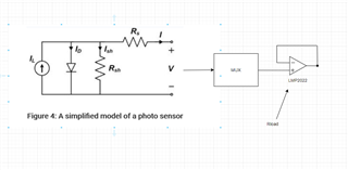
I'm using the CD4051B for a precision sensing application where multiple reference resistors are multiplexed into the reference pins on an ADC. 

Channels 0-8 connect to the high side node of the reference resistors and the common node goes to a zero-drift op-amp used as a buffer before driving the Vref pins of the ADC.

The excitation currents for the RTDs will be in the 10s of microamps, and so I need to account for all error sources.

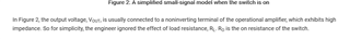
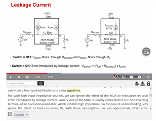
I have read from a TI presentation that leakage current will act as a current source to either the input or out and create an offset based on the load or source resistance:

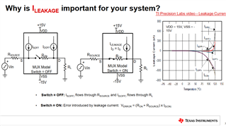
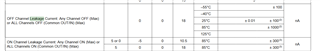
However, this doesn't seem right for this IC as the datasheet states:

If the TI presentation is correct then i would have to multiply the leakage current by an extremely high load resistance which is made up from the input impedance on the buffer op amp itself.

Should i be concerned about leakage even if the buffering make the circuit extremely high impedance?

  • Hi Aidan,

    I would not describe the multiplexer as "sourcing" any current as it is just a passive device. Leakage is more of an appropriate representation as the leakage is made up of currents from the protection diodes, parasitics, and leakage from the internal gates themselves (no circuitry actively driving a current).

    However, you will need to account for this error in your calibration since the off leakage will impact downstream devices. As you mentioned, there will be some offset errors, but will be exactly determined by the load you are connecting and the voltage present on that load. While it may not be a very large offset, in precision applications it could make a difference, so accounting for this error is definitely needed then.

    Thanks!

    Bryan

  • Got it, thanks for the response.

    Would you be able to clarify how this interacts with a very high impedance output though?  If you have xnA to a buffer stage, it doesn't seem right to multiply the effective Rload by the leakage.

  • Hi Aidan,

    So we actually have a good write up on a similar topic you can reference here:

    https://e2e.ti.com/blogs_/archives/b/precisionhub/posts/does-a-low-leakage-multiplexer-really-matter-in-a-high-impedance-plc-system

    Basically, the source resistance plus the load times the leakage current will be your offset. Do you know what your actual load resistance will be? What does extremely high mean? For reference, the CD4051 has a typical leakage current of 10pA, so at 1M input impedance you would see around 10uV of offset. If you need higher precision in your system, you can look into higher precision multiplexers (such as the TMUX1108).

    Thanks!

    Bryan

  • Hi Bryan,

    I have seen this reference, but here is what's making me question just modeling things as current sources:

    That reference you posted says that it can be ignored given the high input impedance of an amplifier.

    Additionally, I have to consider the worst-case scenario where the leakgaes are way higher than 10pA:

    Is there any resource for the CD4051B that shows the relationship between leakage and temperature as a graph?

  • Hi Aidan,

    I believe you are misinterpreting the reference. The article goes over a situation where the engineer initially dismissed the leakage current, only to find out later on it made a measurable impact on their application. I would re-read the article I linked so you can understand the entire situation and outcome.

    In regards to the relationship between leakage and temperature, we do not have a graph illustrating the exact behavior, but you can extrapolate the approximate leakage performance based on the maximum leakage measurements between 25C and 85C as there is a fairly linear relationship between increasing temperature and increasing leakage current.

    Thanks!

    Bryan

  • Bryan, I have read through the reference, I think you should go back and read it also.  Table 1, which assesses whether or not the engineer can ignore leakage only looks at the impact of the Ro and Rsource, which is shown in equations 1 and 2.  The screenshot I have posted is questioning the assumption about ignoring Rload.  Never in this article is the error from Rload calculated and used to make a claim if it was appropriate for the engineer to ignore this.

    This assumption is reinforced in the TI video that walks through how to calculate error ( read the text shown in the screenshot below):

    If the input resistance to a buffer amp is in the Gohms, then even tiny leakge currents will be a problem when you run through the calc your way.  This is why I believe both references from TI ignore it - because after some point you cannot model the leakage as a current source.

  • Hi Aidan,

    The article references RL, just not in the same terms. It is called RSH in the article:

    With the video, the video oversimplifies the effects of the load resistance as the video is just for basic understanding of what leakage current is and focusses on the impact of just the multiplexer itself (in addition, the loading can be a wide array of values so it was ignored to make sure the main concept of where the current is coming from and what the standalone mux impact is - not system level). In reality, you cannot ignore the load resistance and it will most certainly be impacted based on the leakage current from the multiplexer (which is why it is so crucial to have extremely low leakage performance when being used in an application where even a few uV will be impactful).

    Regardless, like I previously mentioned, the voltage offset will be equivalent to whatever IOFF leakage current you see in your system conditions times the load resistance. So if your load resistance is that high and you need better accuracy with the present configuration, you will either need to accept the accuracy losses, lower the input impedance, or get a higher performing multiplexer with lower leakage current.

    Hope this clears things up!

    Thanks!

    Bryan

  • Everything related to Rsh is on the input side of the MUX.  Rl is on the output side of the mux.  I'm not sure how you can say Rsh is the same.  The magnitude of impedance is so different that I'd be surprised if the current source model held when considering the input going to a buffer.  If it did, then every article would say to never use a buffer like this with the output of a MUX.

    Many ADCs use multiplexers that feed a high impedance buffer, and I'm sure nano-amp leakage values don't turn in offsets that are much greater than the tens of uV value your referencing.

  • Hi Aidan,

    Appreciate the discussion on this. Believe you are correct after re-reading the article!

    Thinking more about this, when the switch is off (the INH pin is toggled in this case to turn every channel to an open state), whatever leakage current is present will still flow through the load resistance, however, it should not matter since in this case you would not be measuring anything (IOFF is taken with all channels in the open state). Moreover, the leakage may be even lower than the spec on the datasheet as there is no voltage bias on these pins and essentially floating (IOFF is taken at some predetermined voltage on the input/output pins). When in the non-disabled state (INH pin toggled low), at least one channel will be selected as ON, and the leakage current will flow in the path of least resistance (in this case mostly through the switch to the source as the input buffer should be sufficiently higher than the source resistance). Hence contributing an offset voltage equivalent to approximately the leakage current times RON.

    Think we are on the same page now.

    Apologize for the confusion.

    Thanks!

    Bryan

  • Aha!  Yes we are on the same page now, thanks for sticking with me here.  Your answer makes sense.  It seems like the simple thing to do is just add another buffer on the input side of the MUX, after the sensor stage, if the leakage get's excessive.