

This article was updated on August 28, 2019.
A very passionate young engineer at a leading programmable logic controller (PLC) manufacturer was designing a multichannel 24-bit analog input module that accepts inputs from high-impedance sensors. He selected a TI 24-bit delta-sigma analog-to-digital converter, the ADS125H02, a 5-V voltage reference and a TI precision amplifier, the OPA192.
When it was time to select a multiplexer, he had three choices - the TI MUX36D04 and two multiplexers (MUX2 and MUX3) from other vendors. Each multiplexer had similar specifications, except for the input leakage current specification, which were 1 pA, 100 pA and 1 nA, respectively (typical value at 25°C).
Initially, the engineer thought that all three looked the same, and that the input leakage current in all three multiplexers was low enough to ignore. He thought he could choose any one of the three and get similar performance from his system.
In this post, you’ll find out if he got away with ignoring the multiplexer’s leakage current.
Figure 1 shows a standard block diagram of a data acquisition system with multiple sensor interfaces.
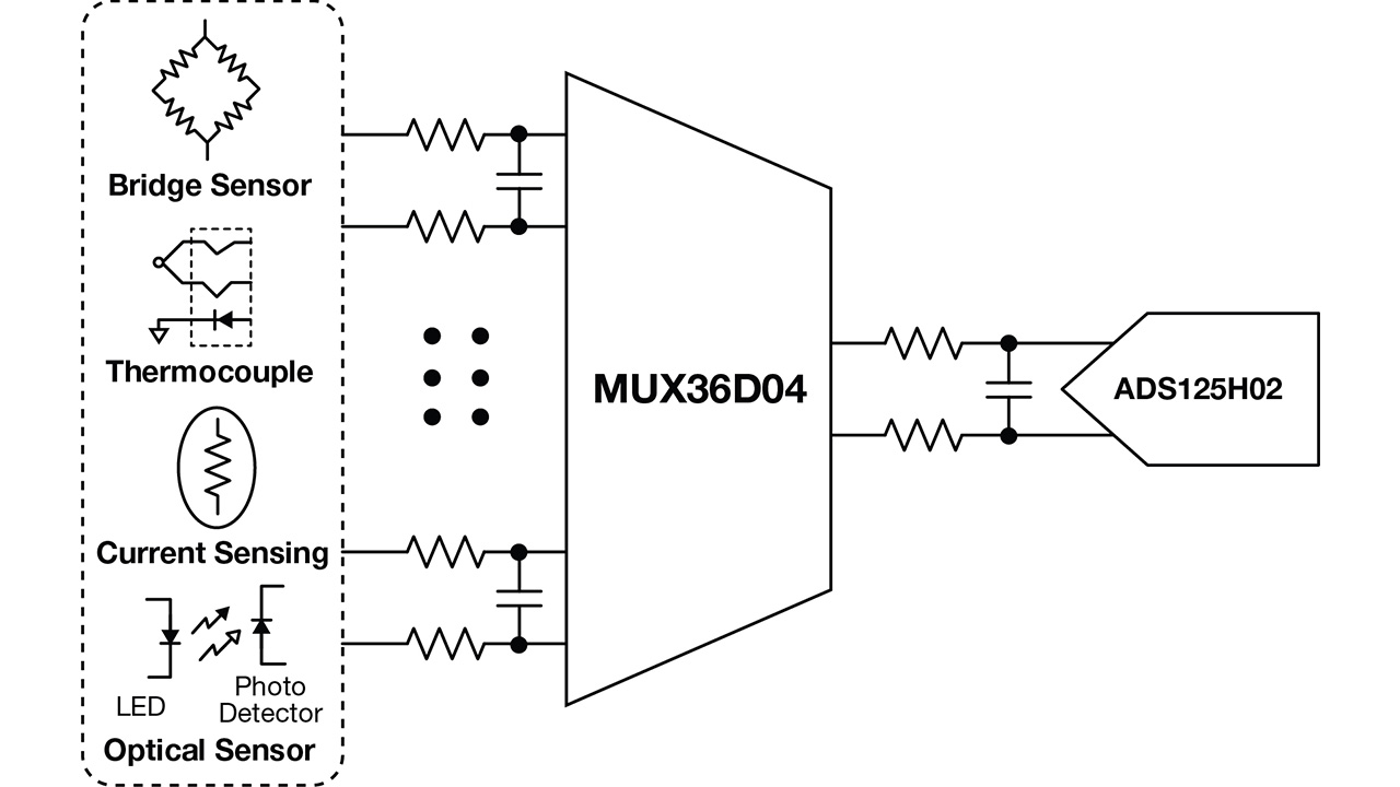
Figure 1: Block diagram of an input signal-conditioning unit in a data-acquisition system
Leakage current: A silent contributor to offset and offset drift errors
Leakage current is an important parameter, as it contributes to DC errors both when the switch is on and when it is off. The multiplexer data sheet has many specifications related to leakage current, including leakage current flowing through the source pin (IS) or the drain pin (ID) when the switch is on or off. Figure 2 shows a simplified model of an analog switch.
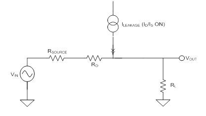
Figure 2: A simplified small-signal model when the switch is on
In Figure 2, the output voltage, VOUT, is usually connected to a noninverting terminal of the operational amplifier, which exhibits high impedance. So for simplicity, the engineer ignored the effect of load resistance, RL. RO is the on resistance of the switch.
When the switch is on, Equation 1 calculates the voltage error introduced by leakage current:
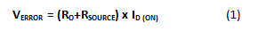
When the switch is off, leakage current flows through the respective terminal (drain or source) and introduces offset error at the output.
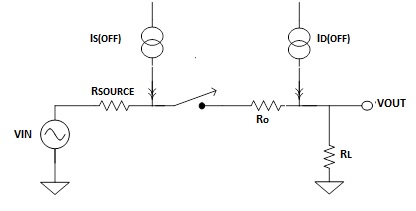
Figure 3: Simplified small-signal model when the switch is off
Leakage current also increases with temperature. All data sheets should include typical plots of leakage current vs. temperature. Although the magnitude of leakage current is very low, it’s a very important parameter to consider when dealing with high input-impedance sensors. So let’s see how this parameter affects system performance.
Pico-amps or Nano-amps of leakage current – one and the same… Well not really
Analog input modules in PLC systems often switch high-input impedance sensors such as pH, optical, humidity, accelerometer and chemical sensors. All of these sensors exhibit input impedance, which can vary from a few hundred of kilo-ohms to few giga-ohms. Take a classic example of a photo sensor, shown in Figure 4.

Figure 4: A simplified model of a photo sensor
In Figure 4, the shunt resistor, Rsh, varies from a few hundreds of kilo-ohms to a few giga-ohms and has an inverse relationship with temperature. Since shunt capacitance is in the order of a few pico-farads, it’s inconsequential and hence not shown in Figure 4.
How leakage current affects system accuracy
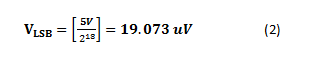
For simplicity, assume that the sensor impedance, Rsh, is 1MΩ. For an 24-bit system referenced to 5V, Equation 2 calculates the minimum resolution or voltage corresponding to 1 least significant bit (LSB) as:
Remember that the engineer had three multiplexers from which to choose, labeled in Table 1 as the MUX36D04, MUX2 and MUX3. Also remember that the leakage current at (25°C/85°C) was the only differentiating factor. For each multiplexer, leakage current flows through input impedance, resulting in offset error and hence affecting overall system accuracy. Table 1 gives you a quick overview of how multiplexers affect measurement accuracy.
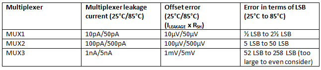
Table 1: Leakage current and its relationship with offset error in terms of LSB
Most sensors have low output voltage; any additional offset introduced due to the input stage can limit the maximum full-scale voltage range that the ADS125H02 can see. From Table 1, it is evident that for a high-accuracy data-acquisition system, even a few hundred pico-amps of input leakage can affect measurement accuracy significantly. Leakage current varies with temperature and Table 1 shows offset error variations at 25°C and 85°C. Photo sensor impedance also changes with light intensity and ambient temperature, so this not only contributes to offset error but also to linearity error.
So the engineer couldn't ignore the leakage current and, as a result, needed to select a low-leakage multiplexer.
Designing multichannel analog input modules that accept high-impedance inputs has its own set of challenges. TI’s MUX36S08 and MUX36D04 ultra-low-leakage analog multiplexers simplify the design of analog input modules by eliminating the need for calibrating their offset errors, while also reducing drift and linearity errors significantly. The MUX36S08 and MUX36D04 have an ultra-low leakage current of 1pA at 25°C. Figure 5 shows the variation of leakage current with temperature for the MUX36S08. (For detailed plots from -40°C to 125°C, see the MUX36S08 data sheet.)
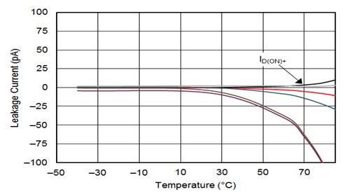
Figure 5: Leakage current ID(ON) variation with temperature for the MUX36S08
In the end, the engineer couldn't get away with ignoring the leakage current; he has to select TI’s low-leakage multiplexer. The MUX36S08 and MUX36D04 options meet the need for low leakage and also offer low on capacitance, low charge injection, rail-to-rail operation and low power consumption.
Let me know what factors you look for in a mux by logging in to post a comment below.
Additional resources
- Get started on your PLC design or other industrial data acquisition design with the TI Designs 16-Bit 400KSPS 4-Channel Multiplexed Data Acquisition Reference Design for High Voltage Inputs, Low Distortion.
- Check out the MUX36S08 evaluation module.
- Download the MUX36S08 TINA-TI™ software reference design.