This thread has been locked.

If you have a related question, please click the "Ask a related question" button in the top right corner. The newly created question will be automatically linked to this question.

TS5MP645: TS5MP645 part to part skew

Part Number: TS5MP645

hello team,
Please help if you know.
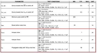
I would like to switch high-speed data of 10ch or more using multiple TS5MP645s.I would like to estimate the part to part skew in that case. But it's not mentioned in the specs.As an estimation method, there is a method of calculating the skew between parts using the maximum and minimum propagation delays and minimum and maximum skews, but the TS5MP645 specification only lists standard values for propagation delay and skew.

  • Hey Hideyoshi,

    There is another method we can provide here. The prop delay is really a product of the load (including the switch). The switch has a pretty low RON and CON so I would expect the load to have more impact here and seeing the variation there may be more worthwhile. That being said, the capacitance itself of the device should remain fairly constant. The RON may vary a bit and is spec'ed in the datasheet. If you follow this FAQ : [FAQ] How do I Approximate Propagation Delay and Channel to Channel Skew in an Analog Switch/Multiplexer?, you can find the bounds of the propagation delay using the typ and max of the RON as your values for your estimation. 
    Note once again though that the prop delay does also depend on your load so it would be worth while to know the load of the system and any variances/tolerances that come with those components. From the device itself though, I would not expect much since the RON and CON are low and flat.

    Thanks,
    Rami

  • Thanks for your comment Rami,

    I read the introduced [FAQ].

    I understand that TS5MP645: Ron & Con are very small, so the propagation delay is determined by the combined value with the external load, and the maximum propagation delay is calculated by the maximum value of Ron and the load capacitance. The skew between parts when using multiple TS5MP645s is TD(min)=Ron(min)*C(Con+Cload), TD(max)=Ron(max)*C(Con+Cload).

    For example here

    Ron(max)=6.5ohm Ron(min)=0ohm (*Ideal value because spec is not stated)

    Con=1.5pF (*Only Typ is listed in the spec)

    Cload=2pF

    →TD(max)=22.75ps

    → TD (min) = 0 ps (ideal value for design margin).

    Therefore, the maximum part-to-part skew is 22.75 ps when the Ron difference of different TS5MP645s varies to the maximum.

  • I wouldn't necessarily use the 0ohm condition/ideal as your min. The device will never produce 0ohms but if this is just to provide extra headroom for design margin then I supposed it wouldn't hurt. I would expect this min RON value will be closer to the RON value (think ~2ohm), which would give roughly a 15.75ps skew. This of course is assuming only a 2pF load and no other trace/board capacitances. As those increase, that overall system skew will increase as well. But this value is a good approximation for just the impact of the device-to-device skew. 

    Thanks,
    Rami

  • Thanks Rami for the explanation of skew between parts.
    I understand that Ron(min) is more than 0 and about 2ohm.
    Ron(min) is not listed in the specifications, a large margin was given to allow for design margins.
    It is my understanding that the load on the board has a lot to do with it. I would like to consider the wiring pattern of the board and the load of the connected IC.
    Thanks,
    HIDE