


For analog switches in many applications, several 100mA of current needs to be supported through the switch (from source to drain, or NO/NC to COM). Many devices already have a max current specified based on ambient temperature, such as the TMUX8212. But if a device specifies with junction temperature or you want to calculate for your specific use case (temperature, supply voltage, channels in parallel) you can use the equations and scheme below.
There are mainly 2 limitations to this max current.
- Inherent metal limitations of the device
- Thermal self-heating limitations
To calculate max current for your specific setup you need the following information:
- Max ambient temperature
- Package thermal coefficients
- On resistance
- Number of channels in parallel
- Any limitations in max current based on temperature from the datasheet
Below is an example using the TMUX1112, the data specified in the datasheet is:
Max TJ = 150°C
RθJA = 146.8°C/W
|
Tj (°C) |
Max IDC (A) |
|
25 |
0.15 |
|
85 |
0.12 |
|
125 |
0.06 |
|
150 |
0.03 |
And we are operating at a 5V supply, all 4 channels in parallel, at 30C ambient temperature. First, we can quickly find the on-resistance at a 5V supply which is 4.9 Ω. Then we calculate the max thermal limitation with the equation below, where n is the number of channels, and Ron is the on resistance. Note we choose a starting Tj for the equation below based on next highest closest row in the table above. So here since the Ta is 30C, we would choose the 85C Tj to compare. This equation can be done recursively at the higher Tj values as needed.
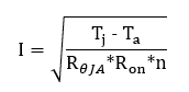
In this example, this would be 138mA. We can compare this to the closest limit in the datasheet and use the smallest number. Above, the limit at 85C Tj is 120mA, so the max current for this scenario is 120mA per channel, or 480mA total. Here we are limited by the inherent metal limitations of the device.
If we do this same example at 50C Ta, the equation above will result in 110mA. So here the max current is actually 110mA per channel, not 120mA, limited by thermals from self-heating.
Similarly you can calculate the Tj and total power dissipated in these examples with the equations below. Note there will be some small power dissipated from the supply current consumption of the device, which is ignored here. For details on how to calculate the max junction temperature of an analog switch, see the FAQ here.
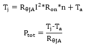
For our example at 30C ambient, the junction temperature of the device will be 71.4C with 280mW of power dissipated. And at 50C ambient, the junction temperature is 85C with 240mW of power dissipated.
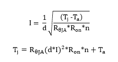
Pulse current can be calculated the same way, but using the duty cycle, d. Typically, pulse current is specified at a 10% duty cycle.
To make designing easier, we have included an excel tool to automatically calculate all this information based on the datasheet information. To use this tool, just enter the info from the datasheet in the cells on the left (columns A-G) and the Max current, junction temperature, and total power will automatically be calculated.