This thread has been locked.

If you have a related question, please click the "Ask a related question" button in the top right corner. The newly created question will be automatically linked to this question.

MPC506: MPC506 dramatic current draw from +/- VIn

Part Number: MPC506
Other Parts Discussed in Thread: SN74LXCH8T245

Tool/software:

Hi, I've got 2 MPC506 devices in parallel and I control the address bits together and the enables opposite using 5V logic levels to sequence through 32 analog input channels.  I power the device with +/-13V and 5V on VRef.  I see my system +13V current and -13V current change significantly every 4 addresses on the muxes.  The pattern of current increase and decrease is the same as I sequence through the first mux and then it repeats for the second mux.  All my analog inputs are driven and are within +/-5V range.  I can change them or set them to zero and it doesn't have a correlation with this current draw.  From lowest to highest current draw, the change is about 20mA which is well above the rating for the mux and we do see heating on the chips.  The mux output is connected to an op-amp and the output steps around from channel to channel as expected and looks clean.  During normal operation I step though the channels at 32ms per channel and there are no slew rate or settling issues.

Any help is appreciated.  If you have any ideas why this current is changing so significantly, I'd appreciate hearing about them!  I can send more design details, if needed.

Thanks,

Ryan

  • Hello Ryan,

    Can you please share a schematic?

    Thanks,

    Nir 

  • I've attached the relevant pages.  Let me know what you think.  By the way, all of the input channels are within the +/-5V range and most are near 0V.  The high current conditions happen even when those 0V channels are selected.

    CCDH GSE Mux Schematic.pdf

  • Hello Ryan,

    Thank you for sharing the schematic. I don't see any issues with it. 

    Where are you measuring the current? Is it that high across the input pins of the device?

    Thanks,

    Nir 

  • Hi Nir,

    Thanks for reviewing it.  I didn't see anything odd either.  We noticed the system +/-13V current jumping around on the lab power supply we're using so we used a current probe to see the finer detail and we see these 125ms steps which is in line with our sample rate/4.  We confirmed the steps correspond to address changes and we have the ability to program the channels that are scanned including setting a single channel.  So for example we see the current on the main PS for  the first 4 channels at 45mA (whole board), and it jumps to 64mA for the second 4 channels.  If we set the channel to 0, 1, 2, or 3, we get a constant non-stepping current of 45mA at the PS and if we go to 4, 5, 6, or 7 the PS current jumps up to 64mA.  This exact pattern repeats when we move to the second mux (EN for the first goes to 0, and 1 for the second).

    We have that RC filter on the +/-13Vs pins of the mux to help reduce noise.  Unfortunately, the R is on the back of the board so we haven't measured across it, but if I just use the scope in AC mode at the power pins, I see the voltage step and decay at these same transitions.  Additionally, using an IR imager, if we dwell on one of the higher current channels and switch to one of the lower current ones, we see both muxes heat up or cool down together, even though one is disabled.

    Not sure if any of that helps.  I feel like we're at the point of replacing the parts but this is the second unit of 2 where we've seen this.  I'm sure the parts were all purchased at the same time.  These have the old Burr Brown logo on them.  Does that mean they were made in the 80s or are they still using that haha?

    Thanks again for looking at this.

    Ryan

  • Hello Ryan,

    Thank you for elaborating it does help a lot. 

    Is it possible for you to replace the two parts with another pair MPC506s and check if the same issue happens? I wonder if this is a system related issue, or a device related issue.

    Thanks,

    Nir 

  • Hi, I tried leaving one mux disabled all the time thru the sequence and we still see the same 4-channel current steps and both chips still get warm during the higher current channels.  We're going to lift one of the output pins to see if that helps - just something to try.  The step after that will be to replace them, but even though we didn't look at the first unit, I'm sure this was happening there, so that makes me think it's a design issue.  Could there be any issue with the logic outputs being slightly higher than VRef causing an issue?  Ours are all driven from the same regulator, but disconnecting our external VRef (5V) could be something to try too.  All the address bits and the enables come from a level shifter (SN74LXCH8T245).  I'll report back when we get changes made to the board.

  • Hello Ryan,

    It could be the case, you can try to float Vref or tie to ground it to see if there is a change. Also I think is worth trying to increase Vref to 10V and the logic voltage to 6V to meet the threshold of the Vah MOS Drive and check the behavior. 

    Thanks,

    Nir 

  • Hi Nir, we finally got fab to lift the Vref pins so they are floated.  The current stepping has ceased and the parts are drawing expected current now and still functioning properly.  We had our P5V0A supply on Vref and P5V0D on the level translators that drive the address and enable bits to the mux.  They come from the same linear regulator, but our separated by a Ferrite Bead.  We don't have much current on either one but they could be slightly different.  Do you have an explanation for why this would cause this behavior?  I might expect something if the the address bits were a diode drop or more above 5V but that wasn't the case, and with the internal reference being 5V, I'm not sure why using that solves the problem unless it's actually higher.  I don't have a way to do MOS levels, but I do have a 5.7V input voltage that we use for our regulators if we need Vref to be a little higher than the address bits.  I'd still like to get a little more clarity on why this was happening.

  • Hello Ryan,

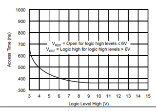
    Since your logic levels were 5V, Vref needed to be open (floating) according to the datasheet. You were exceeding the device limits. After having a deeper look into the datasheet and seeing how the device behaves according to your test results, I believe this seems to be the case.  

    I am assuming the high current and increased temperature was a result of a shoot-trough current. It occurs when CMOS inputs are somewhere between their High and Low voltages, effectively turning on both MOSFETs in the CMOS structure. 

    We have an FAQ about this topic with more information.

    Thanks,

    Nir 

  • Wow, that's it right there, thanks!  I have to say, for such an important parameter, it's hidden well.  I never thought to consult the access time plot and look at the note.  Well, we'll blame Burr Brown for that one.  

    That's what we did and it works great now.  Thanks for working this issue with me.  Great help and good responses.

    Ryan