Other Parts Discussed in Thread: TMUX1108,
I’m developing a multiplexer circuit for potentiostatic analysis using three TMUX1108PWR and one TMUX1109PWR, tested across three prototypes PCBs.
During validation, I observed an unexpected pulsed beep in continuity mode on the B side of the TMUX1109PWR — between pins DB and SnB. This behavior was not present on the A side.
To investigate further, I measured the resistance between Dx and Sx under three conditions:
-
Powered PCB, switch OFF (EN, A0, and A1 measured at 0 V):
-
A side: 1.7 MΩ
-
B side: 260 kΩ
-
-
Unpowered PCB:
-
Results discarded due to unstable floating logic inputs.
-
-
TMUX1109PWR desoldered from PCB:
-
A and B sides both measured >7 MΩ
-
Despite the large difference in off-state resistance, I wouldn’t expect continuity mode to beep. So I measured current flow when shorting Dx to Snx (device powered and switch OFF):
-
A side: ~1 nA
-
B side: ~80 nA
Additionally:
-
DB (pin 9) is connected only to an output terminal — no other components or routing.
-
DA (pin 8) is connected to an output terminal and also to the D terminals of three TMUX1108PWR devices.
For reference, the TMUX1109PWR used in this design was sourced through TI’s sample program.
I plan to replace the TMUX1109PWR in the next prototype. However, I must present the current version to my client tomorrow, and unfortunately, this issue will affect the accuracy of the potentiostatic analysis.
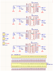
Any other information about this? In the image bellow, Rn's are microcontrolled