- Ask a related questionWhat is a related question?A related question is a question created from another question. When the related question is created, it will be automatically linked to the original question.

I need help interpreting the TS5USBA224 (integrated USB 2.0 and analog audio switch) datasheet.
1) Audio Switch:
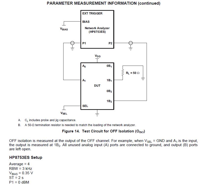
Oiso=-83dB, it means the effect of USB D+/D- signal on the audio channel when USB communication is ongoing. Right?
Xtalk=-83dB here means the crosstalk between left and right channel?
Both specs are taken at 20kHz frequency point?
2) USB Switch:
Oiso=-22dB, it means the effect of Audio L/R signal on the USB channel when audio signal is on transferring. Right?
Xtalk=-21dB here means the crosstalk between D+ and D- channel?
Both specs are taken at 240kHz frequency point?
3) When chip is operating, does D+/R pin output DC level? How much the value?
4) When audio input via USB connector, need insert coupler capacitor between D+/R pin and audio source?
From datasheet, VR, VL range, there should be DC at D+/R pin.
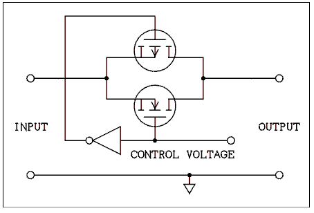
5) From internal block, this switch doesn't have an internal charge pump, will not support a signal swing over the supply voltage, so that means D+/R pin can only be positive signal. Right?