This thread has been locked.

If you have a related question, please click the "Ask a related question" button in the top right corner. The newly created question will be automatically linked to this question.

TS5USBA224 Signal output relation to Vaudio

Other Parts Discussed in Thread: TS5USBA224

Hello E2E,

I have a customer who found that the amplitude of the audio signal is limited to whatever the Vaudio pin Voltage is.  For example, he was feeding a 4Vpp audio signals into the switch chip's R and L input pins and getting a squashed/distorted 3Vpp audio signals out of the D+/R and D-/L output pins when using a 3.3V supply.  This went away when he switched to a 5V supply.  

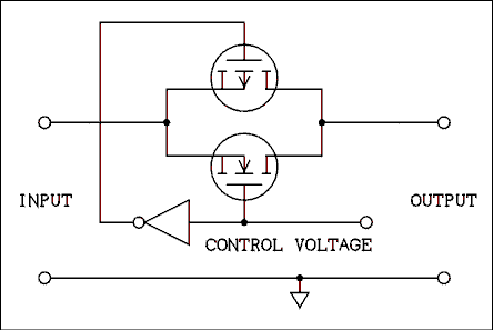
From the datasheet block diagram, it looks like Vaudio is just connected to control logic, but the system seems to mimic behavior of an op-amp.  Why does the TS5USBA224 limit the audio signal swing to whatever the Vaudio pin Voltage is?  We thought there were just simple FET switches inside.

Thank you very much!

Russell

  • Russell,

    You are correct this part is a simple FET switch inside.  The datasheet says you should be able to place a 0 to 5.5 V signal through the switch with Vaudio (supply voltage for the IC). 

    There are two things I am thinking:

    1) Is there something else on the board causing the distortion.  A good way to check is to remover the TS5USBA224 from the board and short the signal path. 

    2) This switch doesn't have an internal charge pump and will not support a signal swing over the supply voltage.  I will need to check with our design team to open the schematic and take a look.  If this is the case you have uncovered an error in the datasheet we will need to quickly address as other people may run into the same issue. 

    Do you have the ability to send any scope shots of the issue?  Vaudio, L/R, and D+/L or D+/R pins? 

    4 Vpp seems rather large for an audio signal through headphone application.  Are you running the signal to a larger speaker? 

    Thank you,

    Adam

  • Stormin Torma!

    Good news.  We found what was wrong on the application size.  

    See his email below:

    "I changed my setup back to a 3.3V power rail for the Vaudio pin, so I could take some screen shots for you.

     I think I discovered that there is no chip problem, it's a problem with the amplified speaker I was feeding with the signal from the TS5USBA224! 

    It turns out that when the amplified speaker is off, the signal through the TS5USBA224 is dragged down and distorted, no matter what the Voltage is on the Vaudio pin of the TS5USBA224."

     One additional question did come up though.

    Does the circuit inside the TS5USBA224 have 2 FETs (back to back) or just one?

    Something like this?

    Thanks!  Have a good weekend.

    Russell

  • Russell,

    I wasn't clear about your question regarding," Does the circuit inside the TS5USBA224 have 2 FETs (back to back) or just one?"  Would you try rephrasing or describe the situation where knowing the answer to your question will be helpful in your design.

    Thank you,

    Adam  

  • Sorry about the confusion.  Here's what I meant by two FETs back to back.

    Russell

  • Russell,

    Yes, the TS5USBA224 has the transmission gate structure you describe above.

    Thank you,
    Adam