This thread has been locked.
If you have a related question, please click the "Ask a related question" button in the top right corner. The newly created question will be automatically linked to this question.
Hello team,
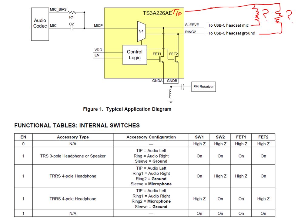
Customer is using regular analog USB-C headset with TS3A226AE and working fine. They are needing to change the regular analog USB-C headset by splitting the headset receiver analog ground from headset microphone analog ground. The change is on the headset side only and needed to avoid crosstalk between receiver and mic.
To do this customer is connecting analog ground of headset receiver to USB-C digital ground. There is no change on TS3A design and no change for headset mic (Ring2 and Sleeve are the same).
The issue now is that the device will not switch to headset mode. So far, it seems that SW detects USB-C headset is plugged and apply mic bias to HS_MIC(MICP) since they can detect the mic bias on Sleeve or/and Ring2. That means S1 is on. However, it seems that either FET1 or FET2 is not on at all because the voltage/waveform of SLEEVE and RING2 is the same. So this issue seems something to do with TS3A226AE. If it can auto switch SLEEVE and RING2, then it should work because there is no change on SLEEVE and RING2 from mic point view.
Can you please help on what may be going on here?
Thanks,
Sepeedah
Seepedah,
1) Do you have a diagram or schematic of the headset and TS3A226AE connections?
2) What does headset mode mean? and what is the other system state its switching from?
3) What is the impedance from the tip to Sleeve and Tip to ring2?
The TS3A226AE automatically configures its internal switch matrix based on the impedance it sees on the tip to sleeve and tip to ring2. This thread goes into more detail on the how the TS3A226AE decides how to configure its switch matrix.
Does TS3A226AE support high impendance microphone (like IPhone 6 earphone ) ? (this post also explains...
The TS3A226AE behaves similar to the TS5A225E. If you look at the TS3A225E datasheet register map you can see that the device recognizes a range of resistances and assigns it a register value. The device then compares the register values to determine if the tip to sleeve (Rsleeve) and tip to ring 2 (R2) resistances are >, <, or = to each other.
In the case you mention R2 = 100k ohms compared to Rsleeve = 102k ohms the audio jack devices will measure those resistances and place them both in the >2800 ohm bucket. Since both resistances will be in the same bucket the audio jack will determine the resistances are equal and configure itself for a 3 pole device grounding both the sleeve and ring 2.
If you need to manually configure the internal switch matrix you can use the TS3A225E or the new TS3A227E that have manual control through I2C commands.
Thank you,
Adam
TJ,
That is correct the headset will need to have the same ground path for the audio jack switch devices to make the impedance measurement which is the way it automatically locates the ground and mic nodes.
If you don't need the automatic detection of the mic and ground lines you can use the manual control feature of the TS3A225E and TS3A227E.
Another option you could try is using a simple cross point switch like the TS3A26746E which you can toggle switch states using a GPIO signal.
Thank you,
Adam