This thread has been locked.

If you have a related question, please click the "Ask a related question" button in the top right corner. The newly created question will be automatically linked to this question.

SN74TVC16222A: Would like to run a simulation of this part with a 25MHz clock to look at the edges and time delay.

Part Number: SN74TVC16222A

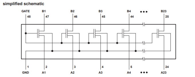
I would like to run a transient sim with the 74TVC16222A or a similar part. I can not find any like it in the Tina library. I do see a HSPICE model for another TVC part but we don't have HSPICE here.

Anyone have a recommendation? Thanks.

  • Tom,

    You could try recreating the circuit equivalent model as in the datasheet. These are essentially just mosfets so something as below should replicate the functionality:


    Or if you're more interested in it's functionality when it's in the ON state and given a known voltage that wont be clamped and just want to see how it would perform with the clock edges you could use the passive component model using the information from the datasheet below:


    For the on capacitance you could you use the Cio(off)/2 for each the source and drain to better represent the Con relative location to the Ron. So something as below would be a diagram for typical usage:


    If your concern is with the edges, the Ron and Con are pretty low here so my feelings are it should be fine from a BW perspective, depending on how much leeway you're allotting. But as always, modeling doesn't hurt. You will definitely need to take in account the load though as this will probably have a bigger impact on this than the switch.

    Thanks,
    Rami

  • Tom,

    There hasn't been a response to this thread in over a week so i'm going to go ahead and close this thread out. Feel free to respond and reopen the thread and i'll be happy to help with any further questions.

    Rami