This thread has been locked.

If you have a related question, please click the "Ask a related question" button in the top right corner. The newly created question will be automatically linked to this question.

TMS320F280037C: TMS320F280037C .syscfg file

Part Number: TMS320F280037C
Other Parts Discussed in Thread: TMS320F280039C

Hello! I am trying to use the .syscfg file in Code Composer Studio to force my microcontroller to boot from FLASH, regardless of the GPIO select pins.

I have two TI microcontrollers, the TMS320F280037C (stand alone) and the TMS320F280039C (on a launchpad board). I have the same workspace I am trying to upload to both units (minus the different linker files and Targetconfig files). I am using the same .syscfg file because the device seelction appears to include both devices. See below.
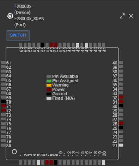
image.png

I am using the DCSM portion of the .syscfg file to attempt the boot from FLASH setting. See image below.
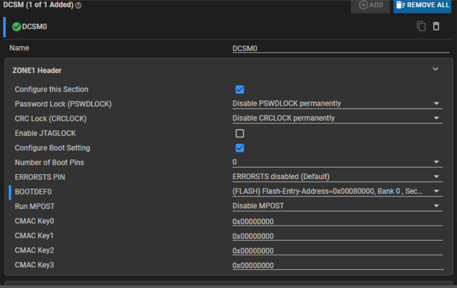
image.png

I am able to acheive the desired result on the TMS320F280039C using these settings. Once I restart the device, my program runs without having to re-upload the code as desired.

However, on the TMS320F280037C, I get this error below when flashing the code, even with a successful build.

image.png

I also am making sure I have the same information in the linker (.cmd) file. The .text in the FLASH is starting at BANK0_SEC0, just like for the TMS320F280039C, where it works fine.

Lastly, when I uncheck the DCSM portion of the .syscfg file, the code does flash to the TMS320F280037C, although not the desired boot from FLASH functionality.

So at this point, I beleive I have narrowed it down to the .syscfg file accessing memory that exists in for the TMS320F280039C, but not the TMS320F280037C; however, I am not able to find anything in the data sheets about what is going on.

Can you please point me in the right direction? Thank you!

  • I think I may have actually figured out what is going on. It does not have to do with the .syscfg file. The 037C device already got flashed once before using the ZONE 1 of the OTP. This is why I am getting that error. To confirm, will using ZONE 2 override what got configured in ZONE 1?

  • Hi Jonathan,

    This is why I am getting that error. To confirm, will using ZONE 2 override what got configured in ZONE 1?

    This is not true; the security mechanisms for both the zones are identical, but independent. The intention is that a third-party would be able to secure their code on the device in a distinct zone. 

    If Z1 of the DCSM is already secured (with CSMPSWDs) on the F280037C device, then you won't be able to re-program the Z1 DCSM region (0x78000 - 0x781FF) unless you unlock the CSM for Z1 beforehand. Once Z1 is unlocked, you can decrement the link pointer to use a different zone select block (ZSB) with new CSMPSWDs and secure regions defined.

    Best,
    Matt  

  • Ohh, that is more involved than I initially thought. What I just did was uncheck the "Configure this Section" in ZONE 1 and copied those same settings for ZONE 2. This worked; the code compiled and flashed to the device with no errors. And now the code runs on start up. Does what I did make sense? There are no issues with that strategy right?

  • Hello,

    That depends on what you already configured in Z1. Z2 cannot access memory regions secured by Z1 and vice versa. When a memory region is secured by a zone, it becomes inaccessible via JTAG or any code running from memory not allocated to the same zone. Data reads or writes in these secure memory regions are permitted only by code secured by the same zone.  If a memory region is secured by Z1, only code executing from Z1 can access it (read/write).

    Best,
    Matt

  • But if you're just programming boot configurations, then Z2 boot configs takes priority over Z1 in the Boot ROM.

    Best,
    Matt