Tool/software:
I have a question regarding setting up the DCSM OTP so that the device standalone boots from Flash.
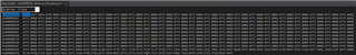
I understand that the Boot Mode Select Pins for the F28003x MCUs are defaulted to GPIO24 and GPIO32 and that these should be pulled HIGH to set the boot mode configuration to FLASH. However, I would like to utilize these GPIO pins for other functions, so I am attempting to configure the boot mode per section 4.5.3.1 Zero Boot Model Select Pins in the TMS320F28003x TRM in addition to the DCSM Security Tool guide SPRACP8A, but I am getting the following error when attempting to flash.
I am setting the ZONE1 header in sysconfig to use 0 Boot pins and for the BOOTDEF0 to be FLASH entry address 0x00080000. I am not configuring the Linkpointer and I am leaving Zone 2 as is. This is the first time I have attempted to flash a build that incorporates the dcsm.asm and dcsm.cmd files generated by sysconfig, so I don't get why it is informing me that I am attempting to program locations that have already been programmed.
Possible causes/fixes for this error?
Is there a method for retrieving the DCSM OTP settings in realtime from the device?
Current Sysconfig Settings:
Keep in mind that I am using v4.03.00 of C2000ware and v12.3.0 of CCS.
Appreciate any help.
Hi Jacob,
Our syscfg DCSM tool expert is Out of Office and shall be back in couple of days. I can direct you to few E2E threads with similar issues -
Thanks
Aswin
Hi Jacob,
Apologies for the delayed reply. I am confused as to why you are seeing this error as well. Could you connect to the device and look at the memory browser at address 0x78000 onward and send a screenshot of what you see?
Thank you,
Luke
Hi Jacob,
Perhaps your dcsm.asm file is attempting to program all Fs at address 0x78004. Could you share the generated dcsm.asm and dcsm.cmd files as well?
Thank you,
Luke
Luke,
See below.
dcsm.cmd:
/* this linker command file is to be included if user wants to use the DCSM feature on the device * DCSM means Dual Zone Code Security Module. * This linker command file works as an addendum ot the already existing Flash/RAM linker command file * that the project has. * The sections in the *_ZoneSelectBlock.asm source file is linked as per the commands given in the file * NOTE - please note fill=0xFFFF, this helps if users include this file in the project by mistake and * doesn't provide the needed proper *_ZoneSelectBlock.asm sources . * Please refer to the Blinky DCSM example in the controlsuite examples for proper usage of this. * * Once users are confident that they want to program the passwords in OTP, the DSECT section type can be removed. * */ MEMORY { PAGE 0 : /* Program Memory */ /* Z1 OTP. Z1 password locations / Flash and RAM partitioning */ DCSM_OTP_Z1_LINKPOINTER : origin = 0x78000, length = 0x00006 DCSM_OTP_Z1_JLM_ENABLE : origin = 0x78006, length = 0x00002 DCSM_OTP_Z1_GPREG : origin = 0x78008, length = 0x00008 DCSM_OTP_Z1_PSWDLOCK : origin = 0x78010, length = 0x00002 DCSM_OTP_Z1_CRCLOCK : origin = 0x78012, length = 0x00002 DCSM_OTP_Z1_JTAG_PSWDH : origin = 0x78014, length = 0x00004 DCSM_OTP_Z1_CMAC_KEY : origin = 0x78018, length = 0x00008 /* DCSM Z1 Zone Select Contents (!!Movable!!) */ DCSM_ZSEL_Z1_P0 : origin = 0x78020, length = 0x000020 /* Z2 OTP. Z2 password locations / Flash and RAM partitioning */ DCSM_OTP_Z2_LINKPOINTER : origin = 0x78200, length = 0x00006 DCSM_OTP_Z2_RSVD : origin = 0x78206, length = 0x00002 DCSM_OTP_Z2_GPREG : origin = 0x78208, length = 0x00008 DCSM_OTP_Z2_PSWDLOCK : origin = 0x78210, length = 0x00002 DCSM_OTP_Z2_CRCLOCK : origin = 0x78212, length = 0x00002 DCSM_OTP_Z2_RSVD1 : origin = 0x78214, length = 0x0000C /* DCSM Z2 Zone Select Contents (!!Movable!!) */ DCSM_ZSEL_Z2_P0 : origin = 0x78220, length = 0x000020 } SECTIONS { dcsm_otp_z1_linkpointer : > DCSM_OTP_Z1_LINKPOINTER PAGE = 0, type = DSECT dcsm_otp_z1_gpreg : > DCSM_OTP_Z1_GPREG PAGE = 0 dcsm_otp_z1_pswdlock : > DCSM_OTP_Z1_PSWDLOCK PAGE = 0 dcsm_otp_z1_crclock : > DCSM_OTP_Z1_CRCLOCK PAGE = 0 dcsm_otp_z1_jlm_enable : > DCSM_OTP_Z1_JLM_ENABLE, PAGE = 0 dcsm_otp_z1_jtag_pswdh : > DCSM_OTP_Z1_JTAG_PSWDH, PAGE = 0, type = DSECT dcsm_otp_z1_cmac_key : > DCSM_OTP_Z1_CMAC_KEY, PAGE = 0 dcsm_zsel_z1 : > DCSM_ZSEL_Z1_P0 PAGE = 0, type = DSECT dcsm_otp_z2_linkpointer : > DCSM_OTP_Z2_LINKPOINTER PAGE = 0, type = DSECT dcsm_otp_z2_gpreg : > DCSM_OTP_Z2_GPREG PAGE = 0, type = DSECT dcsm_otp_z2_pswdlock : > DCSM_OTP_Z2_PSWDLOCK PAGE = 0, type = DSECT dcsm_otp_z2_crclock : > DCSM_OTP_Z2_CRCLOCK PAGE = 0, type = DSECT dcsm_rsvd_z2 : > DCSM_OTP_Z2_RSVD, PAGE = 0, type = DSECT dcsm_rsvd1_z2 : > DCSM_OTP_Z2_RSVD1, PAGE = 0, type = DSECT dcsm_zsel_z2 : > DCSM_ZSEL_Z2_P0 PAGE = 0, type = DSECT } /* //=========================================================================== // End of file. //=========================================================================== */
dcsm.asm:
;---------------------------------------------------------------------- ; Zone 1 ;---------------------------------------------------------------------- ;; .sect "dcsm_otp_z1_linkpointer" ;; .retain ;; .long 0x00003FFF ;; .long 0x00003FFF ;; .long 0x00003FFF ;; .sect "dcsm_otp_z1_jlm_enable" .retain .long 0xFFFF000F ;Z1OTP_JLM_ENABLE ;; .sect "dcsm_otp_z1_jtag_pswdh" ;; .retain ;; .long 0x4BFFFFFF ;Z1OTP_JTAGPSWDH0 ;; .long 0x3FFFFFFF ;Z1OTP_JTAGPSWDH1 .sect "dcsm_otp_z1_cmac_key" .retain .long 0x00000000 ;Z1OTP_CMACKEY0 .long 0x00000000 ;Z1OTP_CMACKEY1 .long 0x00000000 ;Z1OTP_CMACKEY2 .long 0x00000000 ;Z1OTP_CMACKEY3 .sect "dcsm_otp_z1_pswdlock" .retain .long 0xFB7FFFFF .sect "dcsm_otp_z1_crclock" .retain .long 0x7FFFFFFF .sect "dcsm_otp_z1_gpreg" .retain .long 0x5AFFFFFF ;Z1OTP_GPREG1 = Z1_BOOTPIN .long 0x5AFFFFff ;Z1OTP_GPREG2 .long 0xFFFFFF03 ;Z1OTP_GPREG3 = Z1OTP_BOOTDEF_LOW .long 0xFFFFFFFF ;Z1OTP_GPREG4 = Z1OTP_BOOTDEF_HIGH ;; .sect "dcsm_zsel_z1" ;; .retain ;; .long 0xFFFFFFFF ;Z1OTP_CSMPSWD0 (LSW of 128-bit password) ;; .long 0x4D7FFFFF ;Z1OTP_CSMPSWD1 ;; .long 0xFFFFFFFF ;Z1OTP_CSMPSWD2 ;; .long 0xFFFFFFFF ;Z1OTP_CSMPSWD3 (MSW of 128-bit password) ;; ;; .long 0xAAAAAAAA ;Z1OTP_GRABSECT1 ;; .long 0xAAAAAAAA ;Z1OTP_GRABSECT2 ;; .long 0xAAAAAAAA ;Z1OTP_GRABSECT3 ;; .long 0x0000AAAA ;Z1OTP_GRABRAM1 ;; .long 0xFFFFFFFF ;Reserved ;; .long 0xFFFFFFFF ;Reserved ;; ;; .long 0xFFFFFFFF ;Z1OTP_EXEONLYSECT1 ;; .long 0x0000FFFF ;Z1OTP_EXEONLYSECT2 ;; .long 0x000000FF ;Z1OTP_EXEONLYRAM1 ;; .long 0xFFFFFFFF ;Reserved ;; .long 0xFFFFFFFF ;Z1OTP_JTAGPSWDL0 ;; .long 0x2BFFFFFF ;Z1OTP_JTAGPSWDL1 ;---------------------------------------------------------------------- ; For code security operation,after development has completed, prior to ; production, all other zone select block locations should be programmed ; to 0x0000 for maximum security. ; If the first zone select block at offset 0x10 is used, the section ; "dcsm_rsvd_z1" can be used to program these locations to 0x0000. ; This code is commented out for development. ; .sect "dcsm_rsvd_z1" ; .loop (1e0h) ; .int 0x0000 ; .endloop ;---------------------------------------------------------------------- ; Zone 2 ;---------------------------------------------------------------------- ;; .sect "dcsm_otp_z2_linkpointer" ;; .retain ;; .long 0x00003FFF ;; .long 0x00003FFF ;; .long 0x00003FFF ;; ;; .sect "dcsm_rsvd_z2" ;; .retain ;; .long 0xFFFFFFFF ;Reserved ;; .sect "dcsm_otp_z2_pswdlock" ;; .retain ;; .long 0x1F7FFFFF ;; ;; .sect "dcsm_otp_z2_crclock" ;; .retain ;; .long 0x3FFFFFFF ;; ;; .sect "dcsm_otp_z2_gpreg" ;; .retain ;; .long 0x5AFF1820 ;Z2OTP_GPREG1 = Z2_BOOTPIN ;; .long 0x5AFFFFff ;Z2OTP_GPREG2 ;; .long 0x00000000 ;Z2OTP_GPREG3 = Z2OTP_BOOTDEF_LOW ;; .long 0xFFFFFFFF ;Z2OTP_GPREG4 = Z2OTP_BOOTDEF_HIGH ;; .sect "dcsm_rsvd1_z2" ;; .retain ;; .long 0xFFFFFFFF ;Reserved ;; .long 0xFFFFFFFF ;Reserved ;; ;; .sect "dcsm_zsel_z2" ;; .retain ;; .long 0xFFFFFFFF ;Z2OTP_CSMPSWD0 (LSW of 128-bit password) ;; .long 0x1F7FFFFF ;Z2OTP_CSMPSWD1 ;; .long 0xFFFFFFFF ;Z2OTP_CSMPSWD2 ;; .long 0xFFFFFFFF ;Z2OTP_CSMPSWD3 (MSW of 128-bit password) ;; ;; .long 0xAAAAAAAA ;Z2OTP_GRABSECT1 ;; .long 0xAAAAAAAA ;Z2OTP_GRABSECT2 ;; .long 0xAAAAAAAA ;Z2OTP_GRABSECT3 ;; .long 0x0000AAAA ;Z2OTP_GRABRAM1 ;; .long 0xFFFFFFFF ;Reserved ;; .long 0xFFFFFFFF ;Reserved ;; ;; .long 0xFFFFFFFF ;Z2OTP_EXEONLYSECT1 ;; .long 0x0000FFFF ;Z2OTP_EXEONLYSECT2 ;; .long 0x000000FF ;Z2OTP_EXEONLYRAM1 ;; .long 0xFFFFFFFF ;Reserved ;; .long 0xFFFFFFFF ;Reserved ;; .long 0xFFFFFFFF ;Reserved ;---------------------------------------------------------------------- ; For code security operation,after development has completed, prior to ; production, all other zone select block locations should be programmed ; to 0x0000 for maximum security. ; If the first zone select block at offset 0x10 is used, the section ; "dcsm_rsvd_z2" can be used to program these locations to 0x0000. ; This code is commented out for development. ; .sect "dcsm_rsvd_z2" ; .loop (1e0h) ; .int 0x0000 ; .endloop ;---------------------------------------------------------------------- ; End of file ;----------------------------------------------------------------------
Hi Jacob,
I see the issue. Your linkpointer values are commented out in dcsm.asm. When this happens, CCS will attempt to program all Fs at address 0x78000 which will fail since you cannot program bits to a 1 if they are already programmed to a 0.
To fix this you must enable the Zone Header block in SysConfig so that the linkpointer values will not be commented out in your generated code. Make sure you do not program any values in the zone header with unintended values since they will be permanently programmed on the device (with the exception of JTAGLOCK / JLM_ENABLE)
Thank you,
Luke
Luke,
After implementing your suggestion for modifying the sysconfig file to include linkpointer values, I am still seeing a flash error unfortunately. However, I am not seeing the error that I am attempting to program memory locations that have already been programmed now, so I think its a step in the right direction. See below for flash error:
My sysconfig file is as follows:
And the new resulting dcsm.asm and dcsm.cmd files are below:
dcsm.asm:
;---------------------------------------------------------------------- ; Zone 1 ;---------------------------------------------------------------------- .sect "dcsm_otp_z1_linkpointer" .retain .long 0x00003FFF .long 0x00003FFF .long 0x00003FFF .sect "dcsm_otp_z1_jlm_enable" .retain .long 0xFFFF000F ;Z1OTP_JLM_ENABLE ;; .sect "dcsm_otp_z1_jtag_pswdh" ;; .retain ;; .long 0x4BFFFFFF ;Z1OTP_JTAGPSWDH0 ;; .long 0x3FFFFFFF ;Z1OTP_JTAGPSWDH1 .sect "dcsm_otp_z1_cmac_key" .retain .long 0x00000000 ;Z1OTP_CMACKEY0 .long 0x00000000 ;Z1OTP_CMACKEY1 .long 0x00000000 ;Z1OTP_CMACKEY2 .long 0x00000000 ;Z1OTP_CMACKEY3 .sect "dcsm_otp_z1_pswdlock" .retain .long 0xFB7FFFFF .sect "dcsm_otp_z1_crclock" .retain .long 0x7FFFFFFF .sect "dcsm_otp_z1_gpreg" .retain .long 0x5AFFFFFF ;Z1OTP_GPREG1 = Z1_BOOTPIN .long 0x5AFFFFff ;Z1OTP_GPREG2 .long 0xFFFFFF03 ;Z1OTP_GPREG3 = Z1OTP_BOOTDEF_LOW .long 0xFFFFFFFF ;Z1OTP_GPREG4 = Z1OTP_BOOTDEF_HIGH .sect "dcsm_zsel_z1" .retain .long 0xFFFFFFFF ;Z1OTP_CSMPSWD0 (LSW of 128-bit password) .long 0x4D7FFFFF ;Z1OTP_CSMPSWD1 .long 0xFFFFFFFF ;Z1OTP_CSMPSWD2 .long 0xFFFFFFFF ;Z1OTP_CSMPSWD3 (MSW of 128-bit password) .long 0xAAAAAAAA ;Z1OTP_GRABSECT1 .long 0xAAAAAAAA ;Z1OTP_GRABSECT2 .long 0xAAAAAAAA ;Z1OTP_GRABSECT3 .long 0x0000AAAA ;Z1OTP_GRABRAM1 .long 0xFFFFFFFF ;Reserved .long 0xFFFFFFFF ;Reserved .long 0xFFFFFFFF ;Z1OTP_EXEONLYSECT1 .long 0x0000FFFF ;Z1OTP_EXEONLYSECT2 .long 0x000000FF ;Z1OTP_EXEONLYRAM1 .long 0xFFFFFFFF ;Reserved .long 0xFFFFFFFF ;Z1OTP_JTAGPSWDL0 .long 0x2BFFFFFF ;Z1OTP_JTAGPSWDL1 ;---------------------------------------------------------------------- ; For code security operation,after development has completed, prior to ; production, all other zone select block locations should be programmed ; to 0x0000 for maximum security. ; If the first zone select block at offset 0x10 is used, the section ; "dcsm_rsvd_z1" can be used to program these locations to 0x0000. ; This code is commented out for development. ; .sect "dcsm_rsvd_z1" ; .loop (1e0h) ; .int 0x0000 ; .endloop ;---------------------------------------------------------------------- ; Zone 2 ;---------------------------------------------------------------------- ;; .sect "dcsm_otp_z2_linkpointer" ;; .retain ;; .long 0x00003FFF ;; .long 0x00003FFF ;; .long 0x00003FFF ;; ;; .sect "dcsm_rsvd_z2" ;; .retain ;; .long 0xFFFFFFFF ;Reserved ;; .sect "dcsm_otp_z2_pswdlock" ;; .retain ;; .long 0x1F7FFFFF ;; ;; .sect "dcsm_otp_z2_crclock" ;; .retain ;; .long 0x3FFFFFFF ;; ;; .sect "dcsm_otp_z2_gpreg" ;; .retain ;; .long 0x5AFF1820 ;Z2OTP_GPREG1 = Z2_BOOTPIN ;; .long 0x5AFFFFff ;Z2OTP_GPREG2 ;; .long 0x00000000 ;Z2OTP_GPREG3 = Z2OTP_BOOTDEF_LOW ;; .long 0xFFFFFFFF ;Z2OTP_GPREG4 = Z2OTP_BOOTDEF_HIGH ;; .sect "dcsm_rsvd1_z2" ;; .retain ;; .long 0xFFFFFFFF ;Reserved ;; .long 0xFFFFFFFF ;Reserved ;; ;; .sect "dcsm_zsel_z2" ;; .retain ;; .long 0xFFFFFFFF ;Z2OTP_CSMPSWD0 (LSW of 128-bit password) ;; .long 0x1F7FFFFF ;Z2OTP_CSMPSWD1 ;; .long 0xFFFFFFFF ;Z2OTP_CSMPSWD2 ;; .long 0xFFFFFFFF ;Z2OTP_CSMPSWD3 (MSW of 128-bit password) ;; ;; .long 0xAAAAAAAA ;Z2OTP_GRABSECT1 ;; .long 0xAAAAAAAA ;Z2OTP_GRABSECT2 ;; .long 0xAAAAAAAA ;Z2OTP_GRABSECT3 ;; .long 0x0000AAAA ;Z2OTP_GRABRAM1 ;; .long 0xFFFFFFFF ;Reserved ;; .long 0xFFFFFFFF ;Reserved ;; ;; .long 0xFFFFFFFF ;Z2OTP_EXEONLYSECT1 ;; .long 0x0000FFFF ;Z2OTP_EXEONLYSECT2 ;; .long 0x000000FF ;Z2OTP_EXEONLYRAM1 ;; .long 0xFFFFFFFF ;Reserved ;; .long 0xFFFFFFFF ;Reserved ;; .long 0xFFFFFFFF ;Reserved ;---------------------------------------------------------------------- ; For code security operation,after development has completed, prior to ; production, all other zone select block locations should be programmed ; to 0x0000 for maximum security. ; If the first zone select block at offset 0x10 is used, the section ; "dcsm_rsvd_z2" can be used to program these locations to 0x0000. ; This code is commented out for development. ; .sect "dcsm_rsvd_z2" ; .loop (1e0h) ; .int 0x0000 ; .endloop ;---------------------------------------------------------------------- ; End of file ;----------------------------------------------------------------------
dcsm.cmd:
/* this linker command file is to be included if user wants to use the DCSM feature on the device * DCSM means Dual Zone Code Security Module. * This linker command file works as an addendum ot the already existing Flash/RAM linker command file * that the project has. * The sections in the *_ZoneSelectBlock.asm source file is linked as per the commands given in the file * NOTE - please note fill=0xFFFF, this helps if users include this file in the project by mistake and * doesn't provide the needed proper *_ZoneSelectBlock.asm sources . * Please refer to the Blinky DCSM example in the controlsuite examples for proper usage of this. * * Once users are confident that they want to program the passwords in OTP, the DSECT section type can be removed. * */ MEMORY { PAGE 0 : /* Program Memory */ /* Z1 OTP. Z1 password locations / Flash and RAM partitioning */ DCSM_OTP_Z1_LINKPOINTER : origin = 0x78000, length = 0x00006 DCSM_OTP_Z1_JLM_ENABLE : origin = 0x78006, length = 0x00002 DCSM_OTP_Z1_GPREG : origin = 0x78008, length = 0x00008 DCSM_OTP_Z1_PSWDLOCK : origin = 0x78010, length = 0x00002 DCSM_OTP_Z1_CRCLOCK : origin = 0x78012, length = 0x00002 DCSM_OTP_Z1_JTAG_PSWDH : origin = 0x78014, length = 0x00004 DCSM_OTP_Z1_CMAC_KEY : origin = 0x78018, length = 0x00008 /* DCSM Z1 Zone Select Contents (!!Movable!!) */ DCSM_ZSEL_Z1_P0 : origin = 0x78020, length = 0x000020 /* Z2 OTP. Z2 password locations / Flash and RAM partitioning */ DCSM_OTP_Z2_LINKPOINTER : origin = 0x78200, length = 0x00006 DCSM_OTP_Z2_RSVD : origin = 0x78206, length = 0x00002 DCSM_OTP_Z2_GPREG : origin = 0x78208, length = 0x00008 DCSM_OTP_Z2_PSWDLOCK : origin = 0x78210, length = 0x00002 DCSM_OTP_Z2_CRCLOCK : origin = 0x78212, length = 0x00002 DCSM_OTP_Z2_RSVD1 : origin = 0x78214, length = 0x0000C /* DCSM Z2 Zone Select Contents (!!Movable!!) */ DCSM_ZSEL_Z2_P0 : origin = 0x78220, length = 0x000020 } SECTIONS { dcsm_otp_z1_linkpointer : > DCSM_OTP_Z1_LINKPOINTER PAGE = 0 dcsm_otp_z1_gpreg : > DCSM_OTP_Z1_GPREG PAGE = 0 dcsm_otp_z1_pswdlock : > DCSM_OTP_Z1_PSWDLOCK PAGE = 0 dcsm_otp_z1_crclock : > DCSM_OTP_Z1_CRCLOCK PAGE = 0 dcsm_otp_z1_jlm_enable : > DCSM_OTP_Z1_JLM_ENABLE, PAGE = 0 dcsm_otp_z1_jtag_pswdh : > DCSM_OTP_Z1_JTAG_PSWDH, PAGE = 0, type = DSECT dcsm_otp_z1_cmac_key : > DCSM_OTP_Z1_CMAC_KEY, PAGE = 0 dcsm_zsel_z1 : > DCSM_ZSEL_Z1_P0 PAGE = 0 dcsm_otp_z2_linkpointer : > DCSM_OTP_Z2_LINKPOINTER PAGE = 0, type = DSECT dcsm_otp_z2_gpreg : > DCSM_OTP_Z2_GPREG PAGE = 0, type = DSECT dcsm_otp_z2_pswdlock : > DCSM_OTP_Z2_PSWDLOCK PAGE = 0, type = DSECT dcsm_otp_z2_crclock : > DCSM_OTP_Z2_CRCLOCK PAGE = 0, type = DSECT dcsm_rsvd_z2 : > DCSM_OTP_Z2_RSVD, PAGE = 0, type = DSECT dcsm_rsvd1_z2 : > DCSM_OTP_Z2_RSVD1, PAGE = 0, type = DSECT dcsm_zsel_z2 : > DCSM_ZSEL_Z2_P0 PAGE = 0, type = DSECT } /* //=========================================================================== // End of file. //=========================================================================== */
Appreciate any help.
Thanks,
Jacob
Have you changed any settings under "Configure Boot Setting" in SysConfig(inside of Zone Header block)? It seems you have already programmed the GPREG block which is affected by these GUI fields.
This is the first instance that I have tried to flash the MCU with "Configure Boot Setting" Sysconfig fields populated, so I'm not sure how this OTP would have been programmed already if that's the case. Is there any way to check the contents of the GPREG block to see if it is configured for Zero BMSP and to boot from flash?
If Zone1 has been programmed somehow, then if Zone2 is programmed this should override the settings in Zone1 correct? So, I could potentially still be able to configure this as Zero BMSP to boot from flash by programming the Zone2 header?
Hi Jacob,
You can confirm whether values have been programmed at GPREG by observing the contents of the memory browser starting at address 0x78000. Could you take a screenshot of this and share it on this thread?
You're correct, programming custom settings in zone 2 will override settings in zone 1, however I'd recommend not doing this until you confirm what is going on with zone 1 and save the zone 2 method as a last resort.
Thank you,
Luke
Luke,
If I try to program with the dcsm .asm and .cmd files included in the build, then I receive the flash program error that I have posted below and the memory browser is blank.
If I exclude the dcsm .asm and .cmd files from the build and flash, then the memory browser does populate with the values shown below after the flash operation is complete.
Thanks,
Jacob
Hey Jacob, it appears you've programmed custom GPREG values at addresses 0x7800C and 0x7800E. You won't be able to reprogram the GPREG values with your current .cmd and .asm file.
If you uncheck "Configure Boot Setting" in SysConfig, do all of the GPREG values get commented out in the generated dcsm.asm? This is the expected behavior. If this is the case I'm not sure how the GPREG values would've been programmed with the 0x5AFFFFFF values you're seeing in the memory browser.
Thank you,
Luke
Luke,
That is unfortunate that they have already been programmed. I don't recall doing this. The asm file does comment out the GPREG values when I uncheck the Configure Boot Setting box.
;---------------------------------------------------------------------- ; Zone 1 ;---------------------------------------------------------------------- .sect "dcsm_otp_z1_linkpointer" .retain .long 0x00003FFF .long 0x00003FFF .long 0x00003FFF .sect "dcsm_otp_z1_jlm_enable" .retain .long 0xFFFF000F ;Z1OTP_JLM_ENABLE ;; .sect "dcsm_otp_z1_jtag_pswdh" ;; .retain ;; .long 0x4BFFFFFF ;Z1OTP_JTAGPSWDH0 ;; .long 0x3FFFFFFF ;Z1OTP_JTAGPSWDH1 ;; ;; .sect "dcsm_otp_z1_cmac_key" ;; .retain ;; .long 0x00000000 ;Z1OTP_CMACKEY0 ;; .long 0x00000000 ;Z1OTP_CMACKEY1 ;; .long 0x00000000 ;Z1OTP_CMACKEY2 ;; .long 0x00000000 ;Z1OTP_CMACKEY3 ;; .sect "dcsm_otp_z1_pswdlock" .retain .long 0xFB7FFFFF .sect "dcsm_otp_z1_crclock" .retain .long 0x7FFFFFFF ;; .sect "dcsm_otp_z1_gpreg" ;; .retain ;; .long 0x5AFFFFFF ;Z1OTP_GPREG1 = Z1_BOOTPIN ;; .long 0x5AFFFFff ;Z1OTP_GPREG2 ;; .long 0xFFFFFF03 ;Z1OTP_GPREG3 = Z1OTP_BOOTDEF_LOW ;; .long 0xFFFFFFFF ;Z1OTP_GPREG4 = Z1OTP_BOOTDEF_HIGH .sect "dcsm_zsel_z1" .retain .long 0xFFFFFFFF ;Z1OTP_CSMPSWD0 (LSW of 128-bit password) .long 0x4D7FFFFF ;Z1OTP_CSMPSWD1 .long 0xFFFFFFFF ;Z1OTP_CSMPSWD2 .long 0xFFFFFFFF ;Z1OTP_CSMPSWD3 (MSW of 128-bit password) .long 0xAAAAAAAA ;Z1OTP_GRABSECT1 .long 0xAAAAAAAA ;Z1OTP_GRABSECT2 .long 0xAAAAAAAA ;Z1OTP_GRABSECT3 .long 0x0000AAAA ;Z1OTP_GRABRAM1 .long 0xFFFFFFFF ;Reserved .long 0xFFFFFFFF ;Reserved .long 0xFFFFFFFF ;Z1OTP_EXEONLYSECT1 .long 0x0000FFFF ;Z1OTP_EXEONLYSECT2 .long 0x000000FF ;Z1OTP_EXEONLYRAM1 .long 0xFFFFFFFF ;Reserved .long 0xFFFFFFFF ;Z1OTP_JTAGPSWDL0 .long 0x2BFFFFFF ;Z1OTP_JTAGPSWDL1 ;---------------------------------------------------------------------- ; For code security operation,after development has completed, prior to ; production, all other zone select block locations should be programmed ; to 0x0000 for maximum security. ; If the first zone select block at offset 0x10 is used, the section ; "dcsm_rsvd_z1" can be used to program these locations to 0x0000. ; This code is commented out for development. ; .sect "dcsm_rsvd_z1" ; .loop (1e0h) ; .int 0x0000 ; .endloop ;---------------------------------------------------------------------- ; Zone 2 ;---------------------------------------------------------------------- ;; .sect "dcsm_otp_z2_linkpointer" ;; .retain ;; .long 0x00003FFF ;; .long 0x00003FFF ;; .long 0x00003FFF ;; ;; .sect "dcsm_rsvd_z2" ;; .retain ;; .long 0xFFFFFFFF ;Reserved ;; .sect "dcsm_otp_z2_pswdlock" ;; .retain ;; .long 0x1F7FFFFF ;; ;; .sect "dcsm_otp_z2_crclock" ;; .retain ;; .long 0x3FFFFFFF ;; ;; .sect "dcsm_otp_z2_gpreg" ;; .retain ;; .long 0x5AFF1820 ;Z2OTP_GPREG1 = Z2_BOOTPIN ;; .long 0x5AFFFFff ;Z2OTP_GPREG2 ;; .long 0x00000000 ;Z2OTP_GPREG3 = Z2OTP_BOOTDEF_LOW ;; .long 0xFFFFFFFF ;Z2OTP_GPREG4 = Z2OTP_BOOTDEF_HIGH ;; .sect "dcsm_rsvd1_z2" ;; .retain ;; .long 0xFFFFFFFF ;Reserved ;; .long 0xFFFFFFFF ;Reserved ;; ;; .sect "dcsm_zsel_z2" ;; .retain ;; .long 0xFFFFFFFF ;Z2OTP_CSMPSWD0 (LSW of 128-bit password) ;; .long 0x1F7FFFFF ;Z2OTP_CSMPSWD1 ;; .long 0xFFFFFFFF ;Z2OTP_CSMPSWD2 ;; .long 0xFFFFFFFF ;Z2OTP_CSMPSWD3 (MSW of 128-bit password) ;; ;; .long 0xAAAAAAAA ;Z2OTP_GRABSECT1 ;; .long 0xAAAAAAAA ;Z2OTP_GRABSECT2 ;; .long 0xAAAAAAAA ;Z2OTP_GRABSECT3 ;; .long 0x0000AAAA ;Z2OTP_GRABRAM1 ;; .long 0xFFFFFFFF ;Reserved ;; .long 0xFFFFFFFF ;Reserved ;; ;; .long 0xFFFFFFFF ;Z2OTP_EXEONLYSECT1 ;; .long 0x0000FFFF ;Z2OTP_EXEONLYSECT2 ;; .long 0x000000FF ;Z2OTP_EXEONLYRAM1 ;; .long 0xFFFFFFFF ;Reserved ;; .long 0xFFFFFFFF ;Reserved ;; .long 0xFFFFFFFF ;Reserved ;---------------------------------------------------------------------- ; For code security operation,after development has completed, prior to ; production, all other zone select block locations should be programmed ; to 0x0000 for maximum security. ; If the first zone select block at offset 0x10 is used, the section ; "dcsm_rsvd_z2" can be used to program these locations to 0x0000. ; This code is commented out for development. ; .sect "dcsm_rsvd_z2" ; .loop (1e0h) ; .int 0x0000 ; .endloop ;---------------------------------------------------------------------- ; End of file ;----------------------------------------------------------------------
My only course of action now would be to flash to the Zone2 location with the desired header and linkpointer values correct?
Yes, programming custom boot settings in Zone 2 will override the custom settings in Zone 1. After this the boot settings will be permanent.
To test your boot configuration you can use emulation boot before programming the values permanently in OTP.
Thank you,
Luke
Luke,
I tried setting the EMU boot memory to match the Zero BMSP configuration using the EMU_BOOT_FLASH script defined in the F280037.gel file. With the emulator connected, the device is not booting from flash as I understand it should. See below for memory browser for the contents of the EMU boot registers:
Is there another GEL script I need to run to get the board to boot from flash with emulator connected?
I would like to get this to work prior to setting Zone 2 OTP values.
Thanks,
Jacob
Are you triggering a CPU reset in the CCS GUI after configuring the emulation boot registers?
Yes let's make sure this works before you program Zone 2
Thank you,
Luke
Luke,
When i attempt to trigger a CPU reset in the CCS GUI, I am getting a No Source Available error and it appears to not complete the reset:
The OnReset() GEL function is called once a Debug session is initiated, correct? I say this because I see the GEL_TextOut print statements in SetupDCSM() which is called in the OnReset() in the console once i execute a debug session. So if that is the case then the emulation boot registers should be getting read if an emulator is connected during boot, which does not seem to be the case otherwise the device would boot from flash.
When I take a look at the 0x0D00 in the memory browser which should be the EMU-BOOTPIN-CONFIG register, I do see that it contains 0x5AFFFFFF and the EMU-BOOTDEF-LOW registers contains 0x00000003, which should cause the bootloader to boot using a Zero BMSP configuration from Flash at entry point CPU Bank 0, Sector 0 (0x0008 0000) as I understand it.
Is there any way to step through the execution of the boot mode process to ensure it is following the emulation boot flow as defined in Figure 4-2 of the TRM?
Are there any obvious reasons as to why I would be getting the No Source Available error when executing a CPU reset in the CCS GUI? I can obtain the Disassembly code if it is necessary.
Thanks,
Jacob
Jacob,
You can load the boot rom sources and symbols from C2000Ware under libraries/boot_rom/f28003x/rev0. This would allow you to step through to the bootrom execution.
Regards,
Joseph