TMDSEMU200-U: Error -2131 connecting to TMS320DM6446AZWTA

Part Number: TMDSEMU200-U
Other Parts Discussed in Thread: CCSTUDIO, TMS320DM6446,

Hi I'm having somet trouble and would appreciate any help.


Recieved XDS200 brand new friday to replace an older XDS510. Followed small quick start guide included, the desktop weuse is on CCStudio V5.3 which should be compatiable. Checked in device manager and the drivers look to have automatically assigned correctly. Created a new target confid selectring the right connection and device. Try to begin debug and get error -2131.IMG_9388.JPEG
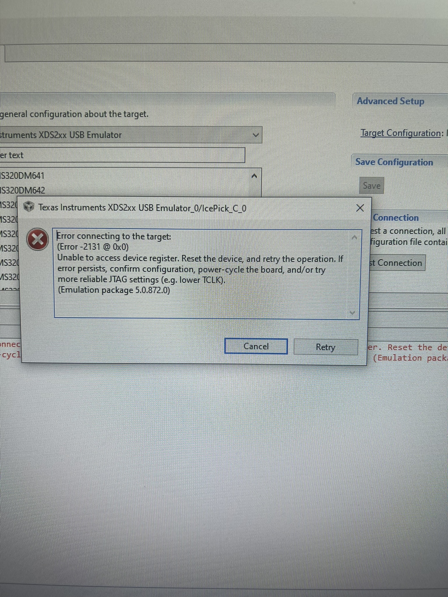
When I attempt to do the test congifuration this the output: [Start].txt 

[Start]

Execute the command:

%ccs_base%/common/uscif/dbgjtag -f %boarddatafile% -r -o -S pathlength -S integrity

[Result]


-----[Perform the standard path-length test on the JTAG IR and DR]-----------

This path-length test uses blocks of 512 32-bit words.

The test for the JTAG IR instruction path-length failed.
The many-ones then many-zeros tested length was 16384 bits.
The many-zeros then many-ones tested length was 0 bits.

The test for the JTAG DR bypass path-length failed.
The JTAG DR bypass scan-path is stuck-at-ones.

-----[Perform the Integrity scan-test on the JTAG IR]------------------------

This test will use blocks of 512 32-bit words.
This test will be applied just once.

Do a test using 0xFFFFFFFF.
Scan tests: 1, skipped: 0, failed: 0
Do a test using 0x00000000.
Test 2 Word 0: scanned out 0x00000000 and scanned in 0xFFFFFFFF.
Test 2 Word 1: scanned out 0x00000000 and scanned in 0xFFFFFFFF.
Test 2 Word 2: scanned out 0x00000000 and scanned in 0xFFFFFFFF.
Test 2 Word 3: scanned out 0x00000000 and scanned in 0xFFFFFFFF.
Test 2 Word 4: scanned out 0x00000000 and scanned in 0xFFFFFFFF.
Test 2 Word 5: scanned out 0x00000000 and scanned in 0xFFFFFFFF.
Test 2 Word 6: scanned out 0x00000000 and scanned in 0xFFFFFFFF.
Test 2 Word 7: scanned out 0x00000000 and scanned in 0xFFFFFFFF.
The details of the first 8 errors have been provided.
The utility will now report only the count of failed tests.
Scan tests: 2, skipped: 0, failed: 1
Do a test using 0xFE03E0E2.
Scan tests: 3, skipped: 0, failed: 2
Do a test using 0x01FC1F1D.
Scan tests: 4, skipped: 0, failed: 3
Do a test using 0x5533CCAA.
Scan tests: 5, skipped: 0, failed: 4
Do a test using 0xAACC3355.
Scan tests: 6, skipped: 0, failed: 5
Some of the values were corrupted - 83.3 percent.

The JTAG IR Integrity scan-test has failed.

-----[Perform the Integrity scan-test on the JTAG DR]------------------------

This test will use blocks of 512 32-bit words.
This test will be applied just once.

Do a test using 0xFFFFFFFF.
Test 1 Word 0: scanned out 0xFFFFFFFF and scanned in 0x00000000.
Test 1 Word 1: scanned out 0xFFFFFFFF and scanned in 0x00000000.
Test 1 Word 2: scanned out 0xFFFFFFFF and scanned in 0x00000000.
Test 1 Word 3: scanned out 0xFFFFFFFF and scanned in 0x00000000.
Test 1 Word 4: scanned out 0xFFFFFFFF and scanned in 0x00000000.
Test 1 Word 5: scanned out 0xFFFFFFFF and scanned in 0x00000000.
Test 1 Word 6: scanned out 0xFFFFFFFF and scanned in 0x00000000.
Test 1 Word 7: scanned out 0xFFFFFFFF and scanned in 0x00000000.
The details of the first 8 errors have been provided.
The utility will now report only the count of failed tests.
Scan tests: 1, skipped: 0, failed: 1
Do a test using 0x00000000.
Scan tests: 2, skipped: 0, failed: 1
Do a test using 0xFE03E0E2.
Scan tests: 3, skipped: 0, failed: 2
Do a test using 0x01FC1F1D.
Scan tests: 4, skipped: 0, failed: 3
Do a test using 0x5533CCAA.
Scan tests: 5, skipped: 0, failed: 4
Do a test using 0xAACC3355.
Scan tests: 6, skipped: 0, failed: 5
Some of the values were corrupted - 83.3 percent.

The JTAG DR Integrity scan-test has failed.

[End]

  • Hi Jay-J,

    Thanks for the details — the scan-path test output tells us exactly what's going on. The stuck-at-ones/stuck-at-zeros pattern in the JTAG IR and DR integrity tests means the emulator (XDS200) can't reliably shift data through the scan path on the target. This is almost always a physical/electrical connection issue, not a software or driver problem — error -2131 is CCS reporting that it can't establish a valid JTAG connection because of this.
    A few things to check, in order of likelihood:
    1. JTAG connector/adapter mismatch The DM6446 EVM typically uses a 14-pin JTAG header, while the XDS200 ships with a 20-pin TI JTAG connector. If you're using a 14-to-20 pin adapter cable, double-check:
      • The adapter is the correct type for this board (not all 14-pin adapters are wired the same).
      • Pin 1 orientation/keying is correctly aligned — a reversed or offset connection is a classic cause of exactly this "stuck-at" pattern.
    2. Board power Confirm the target board is fully powered and stable before you start the debug/test session. An unpowered or brown-out target will produce this same scan failure.
    3. EMU0/EMU1 pin state On the DM6446, EMU0/EMU1 need to be correctly strapped (pulled up) for JTAG emulation boot mode. If these boot-mode pins are misconfigured, the device won't present a valid scan path to the emulator.
    4. Inspect for bent/damaged pins Check both the emulator-side connector and the board header for bent, recessed, or damaged pins — easy to miss visually but will cause intermittent/stuck bits like you're seeing.
    5. Try a lower JTAG clock (TCLK) In your target configuration, under the XDS200 connection's advanced properties, try reducing the JTAG clock speed. Signal integrity issues (long cables, adapters) sometimes only show up at higher clock rates.
    6. Isolate the pod If you have access to another known-good JTAG-capable target, test the XDS200 on it to confirm the emulator itself is functioning correctly. This will tell you whether to focus on the board/cabling side.
    7. Update emulation drivers Since you're on CCS 5.3, go to Help > Check for Updates and make sure you have the latest XDS200 emulation package — older CCS installs sometimes ship outdated FTDI/emulation drivers.
    Given this board was previously running fine with an XDS510, I'd start with #1 and #3 (adapter wiring and EMU0/EMU1 strapping) since those are the most common culprits when swapping emulator types on this platform.
    Let us know what you find and we can narrow it down further.
    Best Regards,
    Zackary Fleenor
  • Hi thanks for the reply. 

    1. I have an adaptor and have confirmed pin orientation. 

    2, I allowed time for board to become fully powered 

    3. These were already set this way 

    4. No issue with pins 

    5. This looks to have provided some success more below

    6. I could try this, do note XDS510 has been used on this PCB to confirm that it is operational.

    7. I will look into this, the PC we have is not on the network for security reasons. 

    As to point 5. I have done some adjusting to the clock speed and repeatedly testing the config. 2.2MHz -2.6MHz seems to consistently allow JTAG DR to consistently pass, I cannot seem to find a speed that gives close to pass results for the IR Integrity test. 

    -----[Perform the standard path-length test on the JTAG IR and DR]-----------

    This path-length test uses blocks of 512 32-bit words.

    The test for the JTAG IR instruction path-length succeeded.
    The JTAG IR instruction path-length is 2 bits.

    The test for the JTAG DR bypass path-length succeeded.
    The JTAG DR bypass path-length is 0 bits.

    -----[Perform the Integrity scan-test on the JTAG IR]------------------------

    This test will use blocks of 512 32-bit words.
    This test will be applied just once.

    Do a test using 0xFFFFFFFF.
    Scan tests: 1, skipped: 0, failed: 0
    Do a test using 0x00000000.
    Scan tests: 2, skipped: 0, failed: 0
    Do a test using 0xFE03E0E2.
    Test 3 Word 0: scanned out 0xFE03E0E2 and scanned in 0xFC07C1C5.
    Test 3 Word 1: scanned out 0xFE03E0E2 and scanned in 0xFC07C1C5.
    Test 3 Word 2: scanned out 0xFE03E0E2 and scanned in 0xFC07C1C5.
    Test 3 Word 3: scanned out 0xFE03E0E2 and scanned in 0xFC07C1C5.
    Test 3 Word 4: scanned out 0xFE03E0E2 and scanned in 0xFC07C1C5.
    Test 3 Word 5: scanned out 0xFE03E0E2 and scanned in 0xFC07C1C5.
    Test 3 Word 6: scanned out 0xFE03E0E2 and scanned in 0xFC07C1C5.
    Test 3 Word 7: scanned out 0xFE03E0E2 and scanned in 0xFC07C1C5.
    The details of the first 8 errors have been provided.
    The utility will now report only the count of failed tests.
    Scan tests: 3, skipped: 0, failed: 1
    Do a test using 0x01FC1F1D.
    Scan tests: 4, skipped: 0, failed: 2
    Do a test using 0x5533CCAA.
    Scan tests: 5, skipped: 0, failed: 3
    Do a test using 0xAACC3355.
    Scan tests: 6, skipped: 0, failed: 4
    Some of the values were corrupted - 66.5 percent.

    The JTAG IR Integrity scan-test has failed.

    -----[Perform the Integrity scan-test on the JTAG DR]------------------------

    This test will use blocks of 512 32-bit words.
    This test will be applied just once.

    Do a test using 0xFFFFFFFF.
    Scan tests: 1, skipped: 0, failed: 0
    Do a test using 0x00000000.
    Scan tests: 2, skipped: 0, failed: 0
    Do a test using 0xFE03E0E2.
    Scan tests: 3, skipped: 0, failed: 0
    Do a test using 0x01FC1F1D.
    Scan tests: 4, skipped: 0, failed: 0
    Do a test using 0x5533CCAA.
    Scan tests: 5, skipped: 0, failed: 0
    Do a test using 0xAACC3355.
    Scan tests: 6, skipped: 0, failed: 0
    All of the values were scanned correctly.

    The JTAG DR Integrity scan-test has succeeded.

    [End]

    
    -----[Perform the standard path-length test on the JTAG IR and DR]-----------
    
    This path-length test uses blocks of 512 32-bit words.
    
    The test for the JTAG IR instruction path-length succeeded.
    The JTAG IR instruction path-length is 2 bits.
    
    The test for the JTAG DR bypass path-length succeeded.
    The JTAG DR bypass path-length is 0 bits.
    
    -----[Perform the Integrity scan-test on the JTAG IR]------------------------
    
    This test will use blocks of 512 32-bit words.
    This test will be applied just once.
    
    Do a test using 0xFFFFFFFF.
    Scan tests: 1, skipped: 0, failed: 0
    Do a test using 0x00000000.
    Scan tests: 2, skipped: 0, failed: 0
    Do a test using 0xFE03E0E2.
    Test 3 Word 0: scanned out 0xFE03E0E2 and scanned in 0xFC07C1C5.
    Test 3 Word 1: scanned out 0xFE03E0E2 and scanned in 0xFC07C1C5.
    Test 3 Word 2: scanned out 0xFE03E0E2 and scanned in 0xFC07C1C5.
    Test 3 Word 3: scanned out 0xFE03E0E2 and scanned in 0xFC07C1C5.
    Test 3 Word 4: scanned out 0xFE03E0E2 and scanned in 0xFC07C1C5.
    Test 3 Word 5: scanned out 0xFE03E0E2 and scanned in 0xFC07C1C5.
    Test 3 Word 6: scanned out 0xFE03E0E2 and scanned in 0xFC07C1C5.
    Test 3 Word 7: scanned out 0xFE03E0E2 and scanned in 0xFC07C1C5.
    The details of the first 8 errors have been provided.
    The utility will now report only the count of failed tests.
    Scan tests: 3, skipped: 0, failed: 1
    Do a test using 0x01FC1F1D.
    Scan tests: 4, skipped: 0, failed: 2
    Do a test using 0x5533CCAA.
    Scan tests: 5, skipped: 0, failed: 3
    Do a test using 0xAACC3355.
    Scan tests: 6, skipped: 0, failed: 4
    Some of the values were corrupted - 66.5 percent.
    
    The JTAG IR Integrity scan-test has failed.
    
    -----[Perform the Integrity scan-test on the JTAG DR]------------------------
    
    This test will use blocks of 512 32-bit words.
    This test will be applied just once.
    
    Do a test using 0xFFFFFFFF.
    Scan tests: 1, skipped: 0, failed: 0
    Do a test using 0x00000000.
    Scan tests: 2, skipped: 0, failed: 0
    Do a test using 0xFE03E0E2.
    Scan tests: 3, skipped: 0, failed: 0
    Do a test using 0x01FC1F1D.
    Scan tests: 4, skipped: 0, failed: 0
    Do a test using 0x5533CCAA.
    Scan tests: 5, skipped: 0, failed: 0
    Do a test using 0xAACC3355.
    Scan tests: 6, skipped: 0, failed: 0
    All of the values were scanned correctly.
    
    The JTAG DR Integrity scan-test has succeeded.
    
    [End]

  • Hi Jay-J,

    Good progress — the DR path is now clean, which confirms the physical connection and power are solid. The IR failure is the remaining blocker, and the pattern you're seeing is a very specific clue.
    What the IR failure pattern tells us:
    Looking at the corrupted data:
    • Scanned out:
      0xFE03E0E2
    • Scanned in:
      0xFC07C1C5
    This is a bit-shift by 1 — every bit has shifted one position. This is a classic symptom of an IR length mismatch in the scan chain definition. The JTAG IR path-length test reported 2 bits, but the DM6446 actually has a longer IR register. The emulator is miscounting the IR length, causing it to shift data by the wrong amount.

    What to try:
    1. Verify IR length in your target configuration In your
    .ccxml
    target config file, check the
    irLength
    or instruction register length setting for the TMS320DM6446. The DM6446 has:
    • ARM926 core — IR length = 4 bits
    • DSP (C64x+) core — IR length = 38 bits (or combined chain length depending on config)
    If the config is set to 2 bits, that's almost certainly the problem. Make sure you selected the correct device —
    TMS320DM6446
    — and not a generic or similar device.
    2. Check your .ccxml for the correct GEL files and device settings Open the target config in CCS and confirm:
    • Connection:
      Texas Instruments XDS200 USB Debug Probe
    • Board/Device:
      TMS320DM6446
      (not DM6441, DM6443, or a generic C64xx)
    3. Update XDS200 firmware/drivers offline Since your PC is air-gapped, you can download the update package on another machine:
    • Go to software-dl.ti.com and search for the XDS200 firmware update or the CCS 5.3 emulation package update
    • Transfer via USB and install manually
    The IR bit-shift error at a consistent clock range strongly suggests a config/device mismatch rather than a hardware fault — especially since the XDS510 previously worked on this board.

    Quick sanity check: When you created the target config, did you select the device as
    TMS320DM6446AZWT
    specifically, or did you use a board-level config? Let us know and we can pinpoint the exact setting to fix.
    Best Regards,
    Zackary Fleenor
  • Hi, Just an update 

    1. I cannot find a setting to change the length in my config, does code composer not auto assign this? 

    2. Yes I have ensured the settings are correct. 

    3. I have updated both the TMDSEMU200-U firmware and the emulation package. This does look to have got us slightly closer see below. 

    After some more testing today I can get to around 9% corruption around 2.0-24MHz. - Just noticed from the results below the test is now setting the path length to 3 bits which may be the reason behind the improved pass rate. If there is a way to adjust this I think it could be the final part needed. 


    [Start]
    
    Execute the command:
    
    %ccs_base%/common/uscif/dbgjtag -f %boarddatafile% -r -o -S pathlength -S integrity
    
    [Result]
    
    
    -----[Perform the standard path-length test on the JTAG IR and DR]-----------
    
    This path-length test uses blocks of 512 32-bit words.
    
    The test for the JTAG IR instruction path-length succeeded.
    The JTAG IR instruction path-length is 3 bits.
    
    The test for the JTAG DR bypass path-length succeeded.
    The JTAG DR bypass path-length is 0 bits.
    
    -----[Perform the Integrity scan-test on the JTAG IR]------------------------
    
    This test will use blocks of 512 32-bit words.
    This test will be applied just once.
    
    Do a test using 0xFFFFFFFF.
    Scan tests: 1, skipped: 0, failed: 0
    Do a test using 0x00000000.
    Scan tests: 2, skipped: 0, failed: 0
    Do a test using 0xFE03E0E2.
    Test 3 Word 5: scanned out 0xFE03E0E2 and scanned in 0xFE03E0F2.
    Test 3 Word 10: scanned out 0xFE03E0E2 and scanned in 0xFF03E0E2.
    Test 3 Word 16: scanned out 0xFE03E0E2 and scanned in 0xFE03F0E2.
    Test 3 Word 21: scanned out 0xFE03E0E2 and scanned in 0x7E03E0E2.
    Test 3 Word 22: scanned out 0xFE03E0E2 and scanned in 0xFE03E0E3.
    Test 3 Word 33: scanned out 0xFE03E0E2 and scanned in 0xFE03E062.
    Test 3 Word 50: scanned out 0xFE03E0E2 and scanned in 0xFE03E0F2.
    Test 3 Word 55: scanned out 0xFE03E0E2 and scanned in 0xFF03E0E2.
    The details of the first 8 errors have been provided.
    The utility will now report only the count of failed tests.
    Scan tests: 3, skipped: 0, failed: 1
    Do a test using 0x01FC1F1D.
    Scan tests: 4, skipped: 0, failed: 2
    Do a test using 0x5533CCAA.
    Scan tests: 5, skipped: 0, failed: 3
    Do a test using 0xAACC3355.
    Scan tests: 6, skipped: 0, failed: 4
    Some of the values were corrupted - 9.3 percent.
    
    The JTAG IR Integrity scan-test has failed.
    
    -----[Perform the Integrity scan-test on the JTAG DR]------------------------
    
    This test will use blocks of 512 32-bit words.
    This test will be applied just once.
    
    Do a test using 0xFFFFFFFF.
    Scan tests: 1, skipped: 0, failed: 0
    Do a test using 0x00000000.
    Scan tests: 2, skipped: 0, failed: 0
    Do a test using 0xFE03E0E2.
    Scan tests: 3, skipped: 0, failed: 0
    Do a test using 0x01FC1F1D.
    Scan tests: 4, skipped: 0, failed: 0
    Do a test using 0x5533CCAA.
    Scan tests: 5, skipped: 0, failed: 0
    Do a test using 0xAACC3355.
    Scan tests: 6, skipped: 0, failed: 0
    All of the values were scanned correctly.
    
    The JTAG DR Integrity scan-test has succeeded.
    
    [End]

    [Start]

    Execute the command:

    %ccs_base%/common/uscif/dbgjtag -f %boarddatafile% -r -o -S pathlength -S integrity

    [Result]


    -----[Perform the standard path-length test on the JTAG IR and DR]-----------

    This path-length test uses blocks of 512 32-bit words.

    The test for the JTAG IR instruction path-length succeeded.
    The JTAG IR instruction path-length is 3 bits.

    The test for the JTAG DR bypass path-length succeeded.
    The JTAG DR bypass path-length is 0 bits.

    -----[Perform the Integrity scan-test on the JTAG IR]------------------------

    This test will use blocks of 512 32-bit words.
    This test will be applied just once.

    Do a test using 0xFFFFFFFF.
    Scan tests: 1, skipped: 0, failed: 0
    Do a test using 0x00000000.
    Scan tests: 2, skipped: 0, failed: 0
    Do a test using 0xFE03E0E2.
    Test 3 Word 5: scanned out 0xFE03E0E2 and scanned in 0xFE03E0F2.
    Test 3 Word 10: scanned out 0xFE03E0E2 and scanned in 0xFF03E0E2.
    Test 3 Word 16: scanned out 0xFE03E0E2 and scanned in 0xFE03F0E2.
    Test 3 Word 21: scanned out 0xFE03E0E2 and scanned in 0x7E03E0E2.
    Test 3 Word 22: scanned out 0xFE03E0E2 and scanned in 0xFE03E0E3.
    Test 3 Word 33: scanned out 0xFE03E0E2 and scanned in 0xFE03E062.
    Test 3 Word 50: scanned out 0xFE03E0E2 and scanned in 0xFE03E0F2.
    Test 3 Word 55: scanned out 0xFE03E0E2 and scanned in 0xFF03E0E2.
    The details of the first 8 errors have been provided.
    The utility will now report only the count of failed tests.
    Scan tests: 3, skipped: 0, failed: 1
    Do a test using 0x01FC1F1D.
    Scan tests: 4, skipped: 0, failed: 2
    Do a test using 0x5533CCAA.
    Scan tests: 5, skipped: 0, failed: 3
    Do a test using 0xAACC3355.
    Scan tests: 6, skipped: 0, failed: 4
    Some of the values were corrupted - 9.3 percent.

    The JTAG IR Integrity scan-test has failed.

    -----[Perform the Integrity scan-test on the JTAG DR]------------------------

    This test will use blocks of 512 32-bit words.
    This test will be applied just once.

    Do a test using 0xFFFFFFFF.
    Scan tests: 1, skipped: 0, failed: 0
    Do a test using 0x00000000.
    Scan tests: 2, skipped: 0, failed: 0
    Do a test using 0xFE03E0E2.
    Scan tests: 3, skipped: 0, failed: 0
    Do a test using 0x01FC1F1D.
    Scan tests: 4, skipped: 0, failed: 0
    Do a test using 0x5533CCAA.
    Scan tests: 5, skipped: 0, failed: 0
    Do a test using 0xAACC3355.
    Scan tests: 6, skipped: 0, failed: 0
    All of the values were scanned correctly.

    The JTAG DR Integrity scan-test has succeeded.

    [End]

  • Hi Jay-J,
    Glad to hear the firmware update moved the IR path‑length from 2 bits to 3 bits and lowered the corruption to ~9 % – that shows we’re getting closer to the correct setting.
    The DM6446 actually has two possible IR lengths depending on which core you’re targeting:
    • ARM926 core: IR length = 4 bits
    • DSP (C64x+) core: IR length = 38 bits (or the combined chain length if both cores are in the scan chain)
    The fact that the IR integrity test still fails with a shifting pattern (bits moving left/right) indicates the emulator is still using an IR length that’s too short. Here’s what to check next:
    1. Confirm which core you intend to debug
      • If you’re debugging the ARM926, make sure the .ccxml is configured for the ARM core and that the irLength is set to 4.
      • If you’re debugging the DSP (C64x+), the irLength should be 38 (or the sum of all devices in the JTAG chain).
    2. Inspect the .ccxml file directly
      Open the target configuration in a text editor and look for an
      irLength
      attribute under the
      <device>
      or
      <instance>
      tag. If it’s missing or set to a low value (like 2 or 3), manually change it to the correct length for your target core and save the file.
    3. Use CCS’s JTAG chain detection
      In CCS, go to Target → JTAG Chain Configuration → Detect. Let CCS read the actual IR length from the hardware and compare it to the value in your .ccxml. If they differ, update the .ccxml to match the detected value.
    4. Verify the device selection
      Ensure the board/device field in the .ccxml reads TMS320DM6446AZWT (or the exact part you have) and not a generic C64xx or a different DM644x variant. An incorrect device pick can cause the wrong default IR length.
    5. Check for multiple devices in the scan chain
      If there are other JTAG devices (e.g., a FPGA, another processor, or a test‑access port) on the same chain, the total IR length is the sum of all devices. Temporarily isolate the DM6446 (by disconnecting other JTAG‑capable parts) to see if the IR length matches the expected 4 or 38 bits.
    6. Re‑run the integrity test
      After making any changes, power cycle the board, reconnect the emulator, and rerun the JTAG IR integrity scan. You should see the failure percentage drop dramatically (ideally to 0 %) once the IR length matches the hardware.
    Best Regards,
    Zackary Fleenor