This thread has been locked.

If you have a related question, please click the "Ask a related question" button in the top right corner. The newly created question will be automatically linked to this question.

C55xx: Error connecting to the target: (Error -1063 @ 0x0) Device ID is not recognized or is not supported by driver

Other Parts Discussed in Thread: TMS320C5535

I have an issue trying to connect XDS100v2 emulator to a custom board with two C5535 DSPs.
I used same schematics as ezDSP5535 with both DSPs in JTAG daisy chain, except that EMU<0,1> are connected in parallel to both DSPs with pull-up and then connected to ADBUS6, ACBUS4 respectively on FTDI device. FTDI EEPROM device has been configured using MProg.

I use CCS V5.3.0.00090.

DBGJTAG test connection passes OK (see output below)

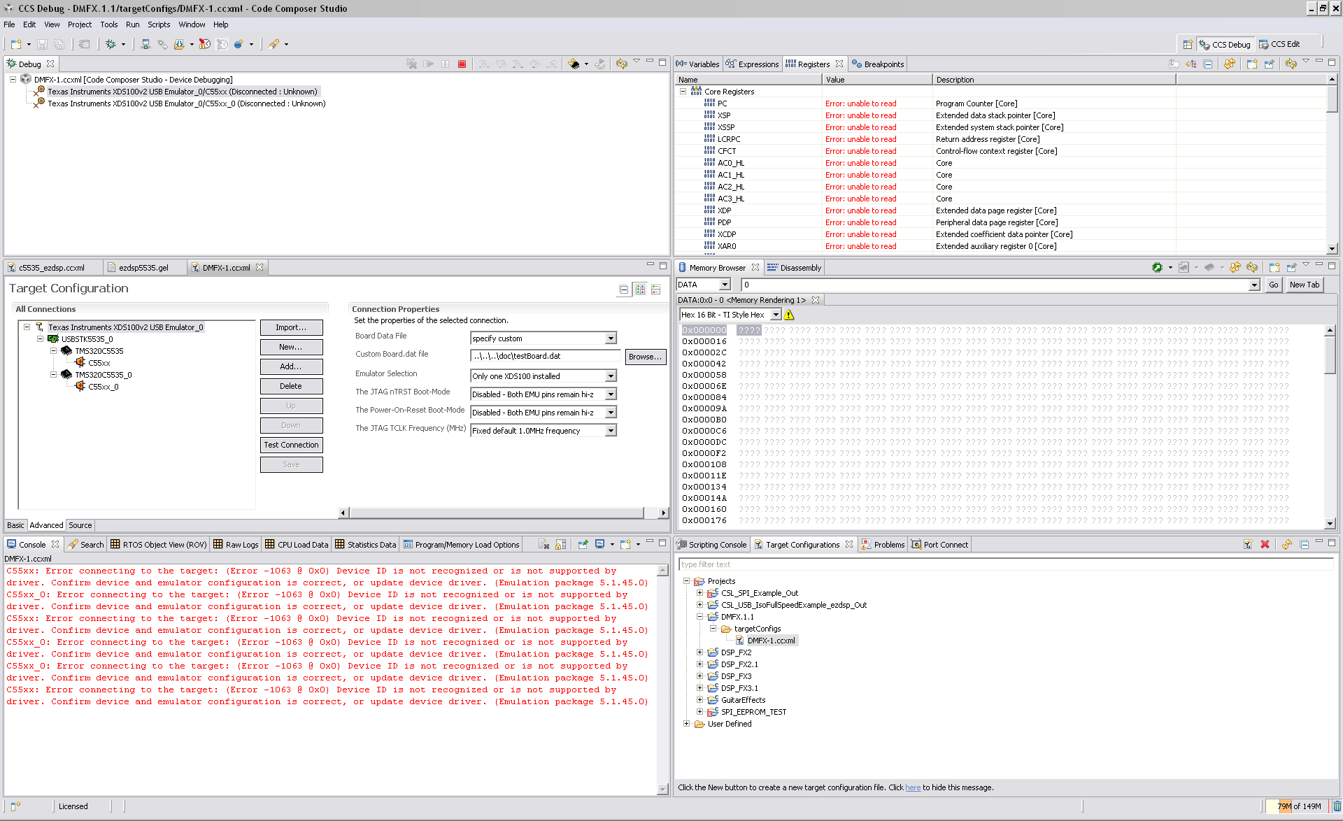
When I try to connect to any of the two targets I get the following error:

C55xx: Error connecting to the target: (Error -1063 @ 0x0) Device ID is not recognized or is not supported by driver. Confirm device and emulator configuration is correct, or update device driver. (Emulation package 5.1.45.0)

Result is the same using the ezDSP5535 GEL file or without GEL file.


I use the following custom Board Data File:

# config version=3.5
$ sepk
pod_drvr=jioserdesusb.dll
pod_port=0
$ /
$ product
title="Texas Instruments XDS100v2 USB"
alias=TI_XDS100v2_USB
name=FTDI_FT2232
$ /
$ ftdi_ft2232
usb_vid=0x0403
usb_pid=0xa6d0
gpio_l0="TRSTn,Active_Low"
gpio_l1="EMU_Pin_Enable,Active_Low"
gpio_l2="EMU_Pin_0,Active_Low"
gpio_l3="Adaptive_Clock,Active_High"
gpio_h0="SRSTn,Active_High"
gpio_h1="SRSTn_In,Active_Low"
gpio_h2="Power_Loss_Detect,Active_Low"
gpio_h3="Power_Loss_Reset,Active_High"
gpio_h4="EMU_Pin_1,Active_Low"
gpio_h5="Cable_Disconnect,Active_High"
gpio_h6="Loopback,Active_High"
$ /
$ uscif
tdoedge=FALL
jtagboot_mode=disable
jtagboot_value=hiz
powerboot_mode=disable
powerboot_value=hiz
tclk_program=SPECIFIC
tclk_frequency=1.0
loopback_mode=disable
loopback_value=disable
$ /
@ c55xx family=tms320c55xx irbits=38 drbits=1
@ c55xx_0 family=tms320c55xx irbits=38 drbits=1
# /

I use the following configuration .ccxml file:

<?xml version="1.0" encoding="UTF-8" standalone="no"?>
<configurations XML_version="1.2" id="configurations_0">


<configuration XML_version="1.2" id="Texas Instruments XDS100v2 USB Emulator_0">
<instance XML_version="1.2" desc="Texas Instruments XDS100v2 USB Emulator_0" href="connections/TIXDS100v2_Connection.xml" id="Texas Instruments XDS100v2 USB Emulator_0" xml="TIXDS100v2_Connection.xml" xmlpath="connections"/>
<connection XML_version="1.2" id="Texas Instruments XDS100v2 USB Emulator_0">
<instance XML_version="1.2" href="drivers/tixds100v2c55x.xml" id="drivers" xml="tixds100v2c55x.xml" xmlpath="drivers"/>
<property Type="choicelist" Value="2" id="dataFileRequired">
<choice value="specify custom">
<property Type="filepathfield" Value="..\..\..\doc\testBoard.dat" id="dataFile"/>
</choice>
</property>
<property Type="choicelist" Value="0" id="The JTAG nTRST Boot-Mode"/>
<property Type="choicelist" Value="0" id="The Power-On-Reset Boot-Mode"/>
<property Type="choicelist" Value="0" id="The JTAG TCLK Frequency (MHz)"/>
<platform XML_version="1.2" id="platform_0">
<instance XML_version="1.2" desc="USBSTK5535_0" href="boards/usbstk5535.xml" id="USBSTK5535_0" xml="usbstk5535.xml" xmlpath="boards"/>
<board XML_version="1.2" description="Spectrum Digital C5535 USB Stick" id="USBSTK5535_0">
<device HW_revision="1" XML_version="1.2" desc="TMS320C5535" description="" id="TMS320C5535_0" partnum="TMS320C5535" simulation="no">
<cpu HW_revision="1.0" XML_version="1.2" desc="C55xx" description="The C55xx CPU" deviceSim="false" id="C55xx" isa="TMS320C55XX">
<property Type="filepathfield" Value="" id="GEL File"/>
<property Type="choicelist" Value="0" id="bypass"/>
</cpu>
</device>
<instance XML_version="1.2" desc="TMS320C5535_1" href="devices/c5535.xml" id="TMS320C5535_1" xml="c5535.xml" xmlpath="devices"/>
<device HW_revision="1" XML_version="1.2" desc="TMS320C5535_0" description="TMS320C5535 16-bit Fixed point ultra low power DSP" id="TMS320C5535_1" partnum="TMS320C5535" simulation="no">
<cpu HW_revision="1.0" XML_version="1.2" desc="C55xx_0" description="The C55xx CPU" deviceSim="false" id="C55xx" isa="TMS320C55XX">
<property Type="choicelist" Value="0" id="bypass"/>
<property Type="filepathfield" Value="" id="GEL File"/>
</cpu>
</device>
</board>
</platform>
</connection>
</configuration>
</configurations>

DBGJTAG Test Connection:

[Start]

Execute the command:

%ccs_base%/common/uscif/dbgjtag -f %boarddatafile% -rv -o -F inform,logfile=yes -S pathlength -S integrity

[Result]


-----[Print the board config pathname(s)]------------------------------------

C:\DOCUME~1\DIEGOD~1\LOCALS~1\APPLIC~1\.TI\
693494126\0\0\BrdDat\testBoard.dat

-----[Print the reset-command software log-file]-----------------------------

This utility has selected a 100- or 510-class product.
This utility will load the adapter 'jioserdesusb.dll'.
The library build date was 'Mar 6 2013'.
The library build time was '21:55:17'.
The library package version is '5.1.45.0'.
The library component version is '35.34.40.0'.
The controller does not use a programmable FPGA.
The controller has a version number of '4' (0x00000004).
The controller has an insertion length of '0' (0x00000000).
This utility will attempt to reset the controller.
This utility has successfully reset the controller.

-----[Print the reset-command hardware log-file]-----------------------------

The scan-path will be reset by toggling the JTAG TRST signal.
The controller is the FTDI FT2232 with USB interface.
The link from controller to target is direct (without cable).
The software is configured for FTDI FT2232 features.
The controller cannot monitor the value on the EMU[0] pin.
The controller cannot monitor the value on the EMU[1] pin.
The controller cannot control the timing on output pins.
The controller cannot control the timing on input pins.
The scan-path link-delay has been set to exactly '0' (0x0000).

-----[The log-file for the JTAG TCLK output generated from the PLL]----------

There is no hardware for programming the JTAG TCLK frequency.

-----[Measure the source and frequency of the final JTAG TCLKR input]--------

There is no hardware for measuring the JTAG TCLK frequency.

-----[Perform the standard path-length test on the JTAG IR and DR]-----------

This path-length test uses blocks of 512 32-bit words.

The test for the JTAG IR instruction path-length succeeded.
The JTAG IR instruction path-length is 12 bits.

The test for the JTAG DR bypass path-length succeeded.
The JTAG DR bypass path-length is 2 bits.

-----[Perform the Integrity scan-test on the JTAG IR]------------------------

This test will use blocks of 512 32-bit words.
This test will be applied just once.

Do a test using 0xFFFFFFFF.
Scan tests: 1, skipped: 0, failed: 0
Do a test using 0x00000000.
Scan tests: 2, skipped: 0, failed: 0
Do a test using 0xFE03E0E2.
Scan tests: 3, skipped: 0, failed: 0
Do a test using 0x01FC1F1D.
Scan tests: 4, skipped: 0, failed: 0
Do a test using 0x5533CCAA.
Scan tests: 5, skipped: 0, failed: 0
Do a test using 0xAACC3355.
Scan tests: 6, skipped: 0, failed: 0
All of the values were scanned correctly.

The JTAG IR Integrity scan-test has succeeded.

-----[Perform the Integrity scan-test on the JTAG DR]------------------------

This test will use blocks of 512 32-bit words.
This test will be applied just once.

Do a test using 0xFFFFFFFF.
Scan tests: 1, skipped: 0, failed: 0
Do a test using 0x00000000.
Scan tests: 2, skipped: 0, failed: 0
Do a test using 0xFE03E0E2.
Scan tests: 3, skipped: 0, failed: 0
Do a test using 0x01FC1F1D.
Scan tests: 4, skipped: 0, failed: 0
Do a test using 0x5533CCAA.
Scan tests: 5, skipped: 0, failed: 0
Do a test using 0xAACC3355.
Scan tests: 6, skipped: 0, failed: 0
All of the values were scanned correctly.

The JTAG DR Integrity scan-test has succeeded.

[End]

  • I used a JTAG scanner application and I was able to properly read the ID codes for both C5535 devices: 0x1B8FE02F.
    To do that I had to set EMU0=0. It did work at any TCLK speed setting.
    So I think that I can say that HW is OK.
    How do I have to configure CCS in order to make the emulator work in a multi-DSP system?
  • There is something weird on the dbgjtag results:

    The test for the JTAG IR instruction path-length succeeded.

    The JTAG IR instruction path-length is 12 bits.

    The test for the JTAG DR bypass path-length succeeded.

    The JTAG DR bypass path-length is 2 bits.


    But actually JTAG IR instruction path-length should be 38-bits and not 12-bits.

  • I tried with CCSv6 on a Windows7 computer and same result, Error -1063.

    I upgraded CCSv5.3 and dbgjtag stopped working, not a win32 application error. I could not revert installation, did not find repositories. I uninstalled latest TI emulator install, and now I have no Emulator. I guess I will have to uninstall and reinstall CCSv5.3 I am worried that CCSv5.5 or CCSv6 don't work on the Windows XP I normally use.

    Other than that big mess when I run a JTAG scan application I have been able to send boundary scan EXTEST instructions to both DSPs and toggle output pins and light LEDs, so that makes me think that my HW is OK.

  • Diego,

    I will move this thread to the CCS forum to see if you can get some assistance on the JTAG scan, since you believe the HW is ok. Thanks for your patience.

    Lali
  • Hi,

    The test connection results you sent in the initial post show successful communications with the target, but the IR path length is indeed strange. One theory is that the EMU pins control how the device's JTAG state machine is configured at power up, and I have seen in the past this cause problems as it configured the device for boundary scan mode instead of debug mode. Information about this should be included in the device's Technical Reference Manual.

    That said, the connections you mentioned seem consistent with section 7.3 of the XDS Target Connection Guide below:
    processors.wiki.ti.com/.../XDS_Target_Connection_Guide

    Another theory is the device is not properly powered up, which may confuse the JTAG debugger as it reads a different device ID (perhaps all zeros) when comparing to its internal value. That seems strange given you can read the device ID using a different JTAG scanner. In this case, I would try to fiddle with the target configuration options "The JTAG nTRST Boot-Mode" and "The Power-On-Reset Boot-Mode" to see if bringing down EMU0 can give you a successful configuration.

    At last, do you have any particular reason do disable the automatic generation of the Board Data File?

    Regards,
    Rafael
  • Hello,

    Thanks for your reply, I have tried all combinations of EMU0, hiz, high, low, and still get the error.

    Actually I have realised that on the ezDSPC5535 kit, EMU0/1 must be always high because they are not connected to the FTDI device outputs.

    EMU0 is sampled with TRST, if it's 0 the DSP is set into Boundary Scan mode, and if it's 1 is set into DSP Emulation mode, which means that there is no way to set the ezDSPC5535 into Boundary scan mode.

    So I guess the right way to connect the DSP Emulator is by setting EMU0 to 1 (or hiz since there is a pull-up) on TRST rising edge.

    My custom design, DMFX-1, can be set into both modes, into DSP Emulation mode I think I get a value of 55 when I shift data into TDI, in Boundary Scan I detect the right ID codes on both DSPs.

    There is no special reason to use a custom board data file, just I thought I could get more control on configuring the board, but I have also tried the automatic mode.

    I have started verifying all pins with a scope one by one, specially power pins and see if I can manage to toggle all output pins.

    The only weird thing I observed so far is that on the second DSP in the chain, USB_LDOO (pin D13) is always 0 instead of 1.3V, and on the first DSP in the chain is 1.3V but after sending a boundary scan EXTEST command, sometimes it goes low, then after some boundary scan manipulation and changes to BYPASS, SAMPLE, EXTEST modes and TRST changes it comes up again.

  • Hello,

    On the DSP that does not provide power supply on USB_LDOO I replaced a jumper and connected USB input power pins to external 1.3V, to see if lack of supply on those USB pins could cause an issue on DSP emulator detection, but still got that damn -1063 error.

    I would like to know if there is any info regarding DSP Emulator commands. I tested the Boundary Scan and it works perfectly, so I would like to be able to send in a DSP Emulator command into the JTAG chain and analyze the response for any clues on what's going on.

  • Issue solved!! 
    EMU0 and EMU1 must NOT be connected to the FTDI device unless there is a CPLD that provides EMU_EN to those pins.

    By probing with a scope I observed that EMU0/1 pins were actually changing from 0 to 1 several times while running DBGTAG or launching emulator, even if they are configured as disabled and hiz.

    I first disconnected EMU0 only, since is the pin that is sampled at TRST_N to decide to set the C55 devices on Boundary Scan or Emulator mode, but it did not work either.

    I then disconnected EMU1, and DBGJTAG returned correct IR adn DR size registers (see DBGJTAG output below).

    I then run CCS emulator and I was able to connect to the targets.

    It has taken me quite some time to figure this out but when it worked I was so happy I almost cried.

    ________________________________________________________

    C:\ti\ccsv5\ccs_base\common\uscif\dbgjtag" -rv -f testBoard.dat -S b

    rokenpath -S integrity -S pathlength,irsize=measure,drsize=measure,analyse=yes -

    A scanpath,verbose=yes

    -----[Print the board config pathname(s)]------------------------------------

    testBoard.dat

    -----[Print the reset-command software log-file]-----------------------------

    This utility has selected a 100- or 510-class product.

    This utility will load the adapter 'jioserdesusb.dll'.

    The library build date was 'Aug 20 2013'.

    The library build time was '22:56:19'.

    The library package version is '5.1.232.0'.

    The library component version is '35.34.40.0'.

    The controller does not use a programmable FPGA.

    The controller has a version number of '4' (0x00000004).

    The controller has an insertion length of '0' (0x00000000).

    This utility will attempt to reset the controller.

    This utility has successfully reset the controller.

    -----[Print the reset-command hardware log-file]-----------------------------

    The scan-path will be reset by toggling the JTAG TRST signal.

    The controller is the FTDI FT2232 with USB interface.

    The link from controller to target is direct (without cable).

    The software is configured for FTDI FT2232 features.

    The controller cannot monitor the value on the EMU[0] pin.

    The controller cannot monitor the value on the EMU[1] pin.

    The controller cannot control the timing on output pins.

    The controller cannot control the timing on input pins.

    The scan-path link-delay has been set to exactly '0' (0x0000).

    -----[Analysing the configure file and the scan-path]------------------------

    File: testBoard.dat

    -------------------

    The configure file indicates one JTAG sub-path should be in the system.

    The configure file indicates 2 JTAG devices should be in the system.

    The pathlength test indicates zero JTAG devices are actually in the system.

    This test cannot analyse the scan-path when the

    configure file and the scan-path do not match.

    -----[Perform the standard path-length test on the JTAG IR and DR]-----------

    This path-length test uses blocks of 512 32-bit words.

    The test for the JTAG IR instruction path-length succeeded.

    The JTAG IR instruction path-length is 76 bits.

    The test for the JTAG DR bypass path-length succeeded.

    The JTAG DR bypass path-length is 2 bits.

    -----[The analysis of the path-length test on the JTAG IR and DR]------------

    The scan-path appears to consist of exactly two devices.

    If the scan-path consists of only TI DSP chips, TI ARM cores

    and TI micro-controllers, or 8-bit long bypassed devices,

    then the measured lengths indicate that both the

    link-delay and scan-path are configured correctly.

    -----[Perform the Broken Path scan-test on the JTAG IR]----------------------

    This test will use blocks of 512 32-bit words.

    This test will be applied just once.

    Do a test using 0xFFFFFFFF.

    Scan tests: 1, skipped: 0, failed: 0

    Do a test using 0x00000000.

    Scan tests: 2, skipped: 0, failed: 0

    All of the values were scanned correctly.

    The JTAG IR Broken Path scan-test has succeeded.

    -----[Perform the Broken Path scan-test on the JTAG DR]----------------------

    This test will use blocks of 512 32-bit words.

    This test will be applied just once.

    Do a test using 0xFFFFFFFF.

    Scan tests: 1, skipped: 0, failed: 0

    Do a test using 0x00000000.

    Scan tests: 2, skipped: 0, failed: 0

    All of the values were scanned correctly.

    The JTAG DR Broken Path scan-test has succeeded.

    -----[Perform the Integrity scan-test on the JTAG IR]------------------------

    This test will use blocks of 512 32-bit words.

    This test will be applied just once.

    Do a test using 0xFFFFFFFF.

    Scan tests: 1, skipped: 0, failed: 0

    Do a test using 0x00000000.

    Scan tests: 2, skipped: 0, failed: 0

    Do a test using 0xFE03E0E2.

    Scan tests: 3, skipped: 0, failed: 0

    Do a test using 0x01FC1F1D.

    Scan tests: 4, skipped: 0, failed: 0

    Do a test using 0x5533CCAA.

    Scan tests: 5, skipped: 0, failed: 0

    Do a test using 0xAACC3355.

    Scan tests: 6, skipped: 0, failed: 0

    All of the values were scanned correctly.

    The JTAG IR Integrity scan-test has succeeded.

    -----[Perform the Integrity scan-test on the JTAG DR]------------------------

    This test will use blocks of 512 32-bit words.

    This test will be applied just once.

    Do a test using 0xFFFFFFFF.

    Scan tests: 1, skipped: 0, failed: 0

    Do a test using 0x00000000.

    Scan tests: 2, skipped: 0, failed: 0

    Do a test using 0xFE03E0E2.

    Scan tests: 3, skipped: 0, failed: 0

    Do a test using 0x01FC1F1D.

    Scan tests: 4, skipped: 0, failed: 0

    Do a test using 0x5533CCAA.

    Scan tests: 5, skipped: 0, failed: 0

    Do a test using 0xAACC3355.

    Scan tests: 6, skipped: 0, failed: 0

    All of the values were scanned correctly.

    The JTAG DR Integrity scan-test has succeeded.

  • Diego,

    I apologize for "disappearing", but external circumstances left me absent from work since Thursday.

    Thank you for posting the solution for this problem; it will surely help others in the future.

    Some board designers decided unilaterally to remove the FPGA device from the reference design of the XDS100v2, which can cause certain problems when the host side device driver resets the FTDI device before connecting (as defined by its documentation). I knew about this causing problems on AM335x devices, and now your report makes it official that another device family can show problems as well.

    Thanks again,
    Rafael
  • Regarding the USB_LDOO (pin D13) output that does not provide 1.3V on its output, it is completely normal. The LDO output must be enabled by setting bit 0 on LDOCNTL register (address 0x7004). What is more strange is the erratic behaviour I observed during Boundary scan, where one DSP sometimes provided 1.3V while the other DSO in the chain had it always disabled.