This thread has been locked.

If you have a related question, please click the "Ask a related question" button in the top right corner. The newly created question will be automatically linked to this question.

CCS: TI XDS100V2 USB Probe Error connecting to the target: (Error -1135 @ 0x0)

Genius 5910 points

Tool/software: Code Composer Studio

Last week I had a working setup. Today I tried again and I got this error message:

I tried multiple XDS100 and multiple targets. with the same result. So I assume it a driver issue. But I can't find any information about error -1135. So any suggestions?

 Thanks.

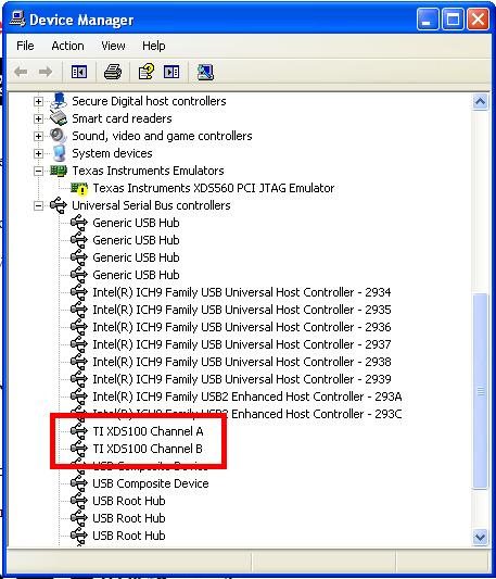
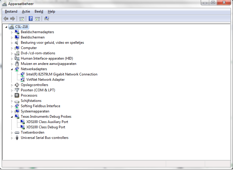
My windows config screen:

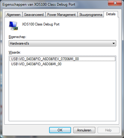
I wonder is the XDS100 config text changed?

  • Hello,
    The error is documented in the below link:
    processors.wiki.ti.com/.../Debugging_JTAG_Connectivity_Problems

    Thanks
    ki
  • Thanks, only is from a working setup. To be sure I also changed the USB cable:
    This is the test connection result:

    [Start: Texas Instruments XDS110 USB Debug Probe_0]

    Execute the command:

    %ccs_base%/common/uscif/dbgjtag -f %boarddatafile% -rv -o -S integrity

    [Result]


    -----[Print the board config pathname(s)]------------------------------------

    C:\Users\spronse\AppData\Local\TEXASI~1\
    CCS\ti\0\0\BrdDat\testBoard.dat

    -----[Print the reset-command software log-file]-----------------------------

    This utility has selected a 100- or 510-class product.
    This utility will load the adapter 'jioxds110.dll'.
    The library build date was 'Feb 22 2017'.
    The library build time was '17:13:34'.
    The library package version is '6.0.579.0'.
    The library component version is '35.35.0.0'.
    The controller does not use a programmable FPGA.

    An error occurred while hard opening the controller.

    -----[An error has occurred and this utility has aborted]--------------------

    This error is generated by TI's USCIF driver or utilities.

    The value is '-260' (0xfffffefc).
    The title is 'SC_ERR_XDS110_OPEN'.

    The explanation is:
    An attempt to connect to the XDS110 failed.
    The cause may be one or more of: no XDS110 is connected, invalid
    firmware update, invalid XDS110 serial number, or faulty USB
    cable. The firmware and serial number may be updated using the
    xdsdfu utility found in the .../ccs_base/common/uscif/xds110
    directory of your installation. View the ReadMe.txt file there
    for instructions.

    [End: Texas Instruments XDS110 USB Debug Probe_0]
  • I think this is the problem:

    How is it possible that this is changed?

  • Any suggestions?

    Thanks!

  • Some extra info:

    It a XDS100V2

    I'm using CSS 6.1.1 and 7.1.0 with Emulation package 6.0.579.0

    PID/VID value

    More test connection results:

    [Start: Texas Instruments XDS100v2 USB Emulator_0]

    Execute the command:

    %ccs_base%/common/uscif/dbgjtag -f %boarddatafile% -rv -o -F inform,logfile=yes -S pathlength -S integrity


    [Result]


    -----[Print the board config pathname(s)]------------------------------------


    C:\Users\spronse\AppData\Local\TEXASI~1\

        CCS\ti\0\0\BrdDat\testBoard.dat


    -----[Print the reset-command software log-file]-----------------------------


    This utility has selected a 100- or 510-class product.

    This utility will load the adapter 'jioserdesusb.dll'.

    The library build date was 'Feb 22 2017'.

    The library build time was '17:13:34'.

    The library package version is '6.0.579.0'.

    The library component version is '35.35.0.0'.

    The controller does not use a programmable FPGA.

    The controller has a version number of '4' (0x00000004).

    The controller has an insertion length of '0' (0x00000000).

    This utility will attempt to reset the controller.

    This utility has successfully reset the controller.


    -----[Print the reset-command hardware log-file]-----------------------------


    The scan-path will be reset by toggling the JTAG TRST signal.

    The controller is the FTDI FT2232 with USB interface.

    The link from controller to target is direct (without cable).

    The software is configured for FTDI FT2232 features.

    The controller cannot monitor the value on the EMU[0] pin.

    The controller cannot monitor the value on the EMU[1] pin.

    The controller cannot control the timing on output pins.

    The controller cannot control the timing on input pins.

    The scan-path link-delay has been set to exactly '0' (0x0000).


    -----[The log-file for the JTAG TCLK output generated from the PLL]----------


    There is no hardware for programming the JTAG TCLK frequency.


    -----[Measure the source and frequency of the final JTAG TCLKR input]--------


    There is no hardware for measuring the JTAG TCLK frequency.


    -----[Perform the standard path-length test on the JTAG IR and DR]-----------


    This path-length test uses blocks of 64 32-bit words.


    The test for the JTAG IR instruction path-length failed.

    The JTAG IR instruction scan-path is stuck-at-ones.


    The test for the JTAG DR bypass path-length failed.

    The JTAG DR bypass scan-path is stuck-at-ones.


    -----[Perform the Integrity scan-test on the JTAG IR]------------------------


    This test will use blocks of 64 32-bit words.

    This test will be applied just once.


    Do a test using 0xFFFFFFFF.

    Scan tests: 1, skipped: 0, failed: 0

    Do a test using 0x00000000.

    Test 2 Word 0: scanned out 0x00000000 and scanned in 0xFFFFFFFF.

    Test 2 Word 1: scanned out 0x00000000 and scanned in 0xFFFFFFFF.

    Test 2 Word 2: scanned out 0x00000000 and scanned in 0xFFFFFFFF.

    Test 2 Word 3: scanned out 0x00000000 and scanned in 0xFFFFFFFF.

    Test 2 Word 4: scanned out 0x00000000 and scanned in 0xFFFFFFFF.

    Test 2 Word 5: scanned out 0x00000000 and scanned in 0xFFFFFFFF.

    Test 2 Word 6: scanned out 0x00000000 and scanned in 0xFFFFFFFF.

    Test 2 Word 7: scanned out 0x00000000 and scanned in 0xFFFFFFFF.

    The details of the first 8 errors have been provided.

    The utility will now report only the count of failed tests.

    Scan tests: 2, skipped: 0, failed: 1

    Do a test using 0xFE03E0E2.

    Scan tests: 3, skipped: 0, failed: 2

    Do a test using 0x01FC1F1D.

    Scan tests: 4, skipped: 0, failed: 3

    Do a test using 0x5533CCAA.

    Scan tests: 5, skipped: 0, failed: 4

    Do a test using 0xAACC3355.

    Scan tests: 6, skipped: 0, failed: 5

    Some of the values were corrupted - 83.3 percent.


    The JTAG IR Integrity scan-test has failed.


    -----[Perform the Integrity scan-test on the JTAG DR]------------------------


    This test will use blocks of 64 32-bit words.

    This test will be applied just once.


    Do a test using 0xFFFFFFFF.

    Scan tests: 1, skipped: 0, failed: 0

    Do a test using 0x00000000.

    Test 2 Word 0: scanned out 0x00000000 and scanned in 0xFFFFFFFF.

    Test 2 Word 1: scanned out 0x00000000 and scanned in 0xFFFFFFFF.

    Test 2 Word 2: scanned out 0x00000000 and scanned in 0xFFFFFFFF.

    Test 2 Word 3: scanned out 0x00000000 and scanned in 0xFFFFFFFF.

    Test 2 Word 4: scanned out 0x00000000 and scanned in 0xFFFFFFFF.

    Test 2 Word 5: scanned out 0x00000000 and scanned in 0xFFFFFFFF.

    Test 2 Word 6: scanned out 0x00000000 and scanned in 0xFFFFFFFF.

    Test 2 Word 7: scanned out 0x00000000 and scanned in 0xFFFFFFFF.

    The details of the first 8 errors have been provided.

    The utility will now report only the count of failed tests.

    Scan tests: 2, skipped: 0, failed: 1

    Do a test using 0xFE03E0E2.

    Scan tests: 3, skipped: 0, failed: 2

    Do a test using 0x01FC1F1D.

    Scan tests: 4, skipped: 0, failed: 3

    Do a test using 0x5533CCAA.

    Scan tests: 5, skipped: 0, failed: 4

    Do a test using 0xAACC3355.

    Scan tests: 6, skipped: 0, failed: 5

    Some of the values were corrupted - 83.3 percent.


    The JTAG DR Integrity scan-test has failed.


    [End: Texas Instruments XDS100v2 USB Emulator_0]


    -          Controlstick TMS320F280F069M

    [Start: Texas Instruments XDS100v2 USB Debug Probe_0]


  • Hi,

    It seems there are a few inconsistencies with your setup. Looking at the first connection error message it seems your target configuration is set to use a XDS110 Debug Probe but you instead have a XDS100 installed. 

    evs said:
    The value is '-260' (0xfffffefc).
    The title is 'SC_ERR_XDS110_OPEN'.

    The explanation is:
    An attempt to connect to the XDS110 failed.

    The change in the device driver string happened during one of the emulation pack versions (previously than version 6.0.579.0) and it is purely cosmetic - it should not affect its functionality.

    The second error message does, in fact, refer to the XDS100 configuration. In this case, make sure you have either configured your board to match the XDS100v1 or XDS100v2. Also, the invalid data read back by the Test Connection routine is mentioned in section 5.13 of the reference sent by Ki before.

    http://processors.wiki.ti.com/index.php/Debugging_JTAG_Connectivity_Problems

  • Thanks for the reply. I tried a lot of thinks to find the problem I tried all options and have read the wiki!
    Again This is from a test setup I worked with for over a year.On Monday it doesn't work anymore I got a couple of F2808x Controlcards and they have the sample problem.
    I installed CCS 7 on a test laptop and the test connection works fine on my original test setup. So I really think that it is a driver issue.
  • evs said:

    This path-length test uses blocks of 64 32-bit words.


    The test for the JTAG IR instruction path-length failed.

    The JTAG IR instruction scan-path is stuck-at-ones.


    The test for the JTAG DR bypass path-length failed.

    The JTAG DR bypass scan-path is stuck-at-ones.


    This type of error usually points to a HW connection/environment issue instead of a driver issue. Please make sure your connections are good. See:

    http://processors.wiki.ti.com/index.php/Debugging_JTAG_Connectivity_Problems#Invalid_data_read_back

  • Somehow solved. I made a new programmer and that solved the problem. So There is a problem in my on old program. The only think I don't understand why did I had the same problem on the 28069M ISO control cards, when I interchange them for testing. They also work also fine now.

    I hate it when this happens so much time lost solving stupid problems,