This thread has been locked.
If you have a related question, please click the "Ask a related question" button in the top right corner. The newly created question will be automatically linked to this question.
Dear experts,
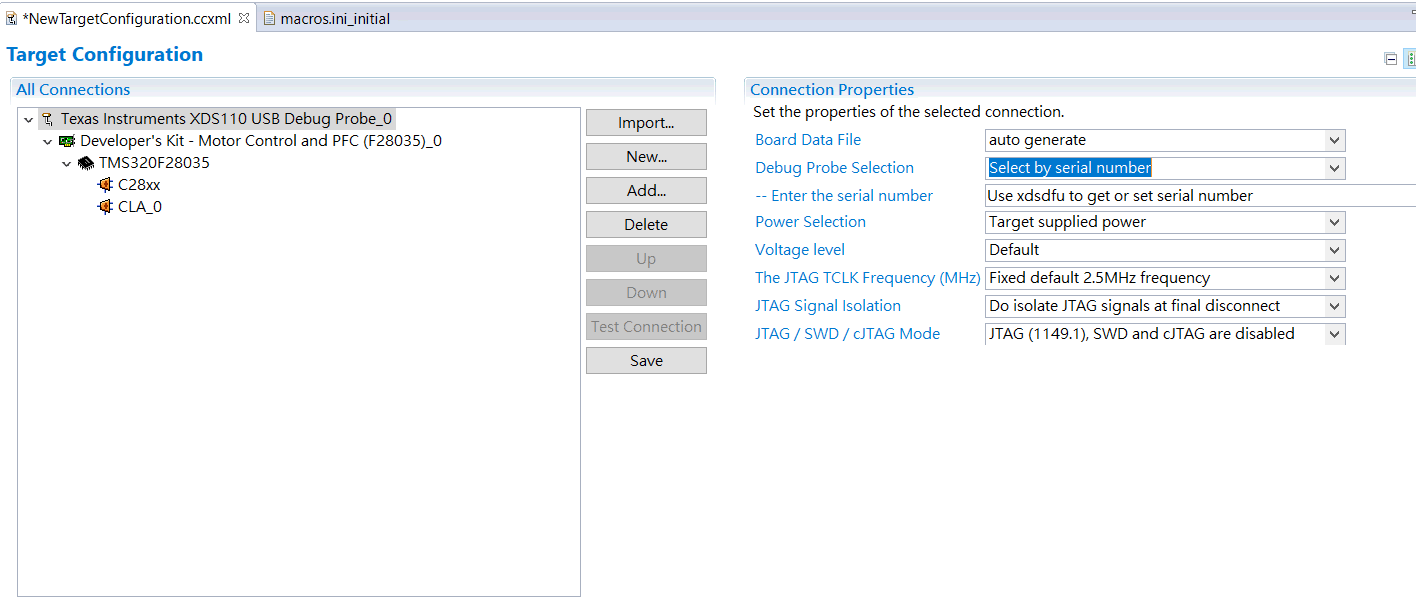
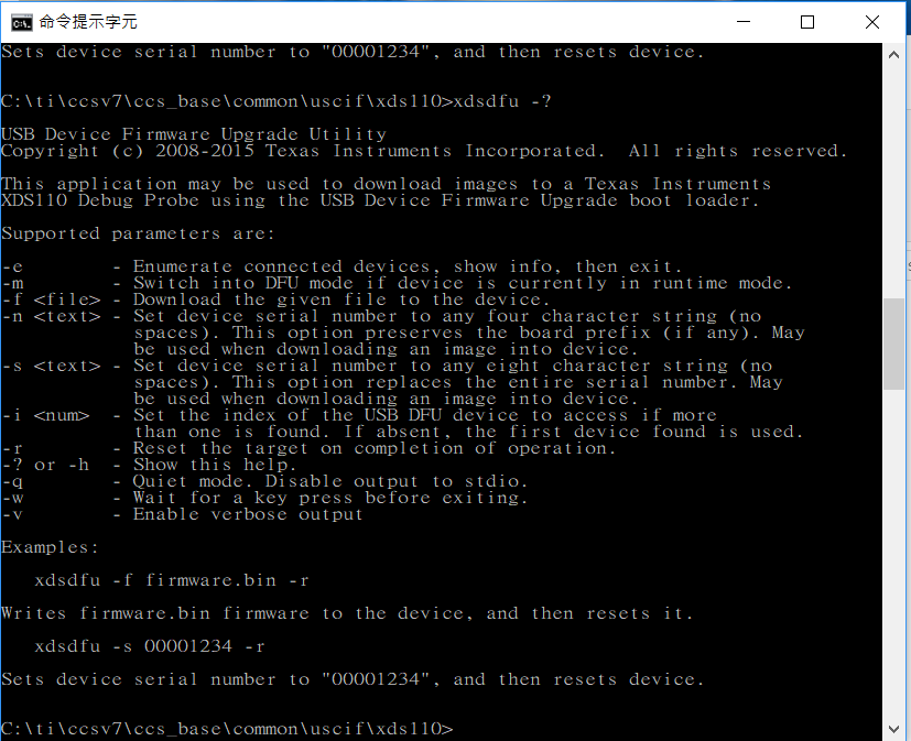
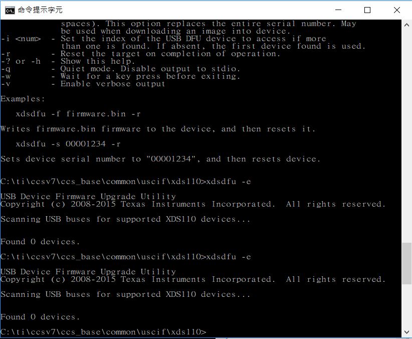
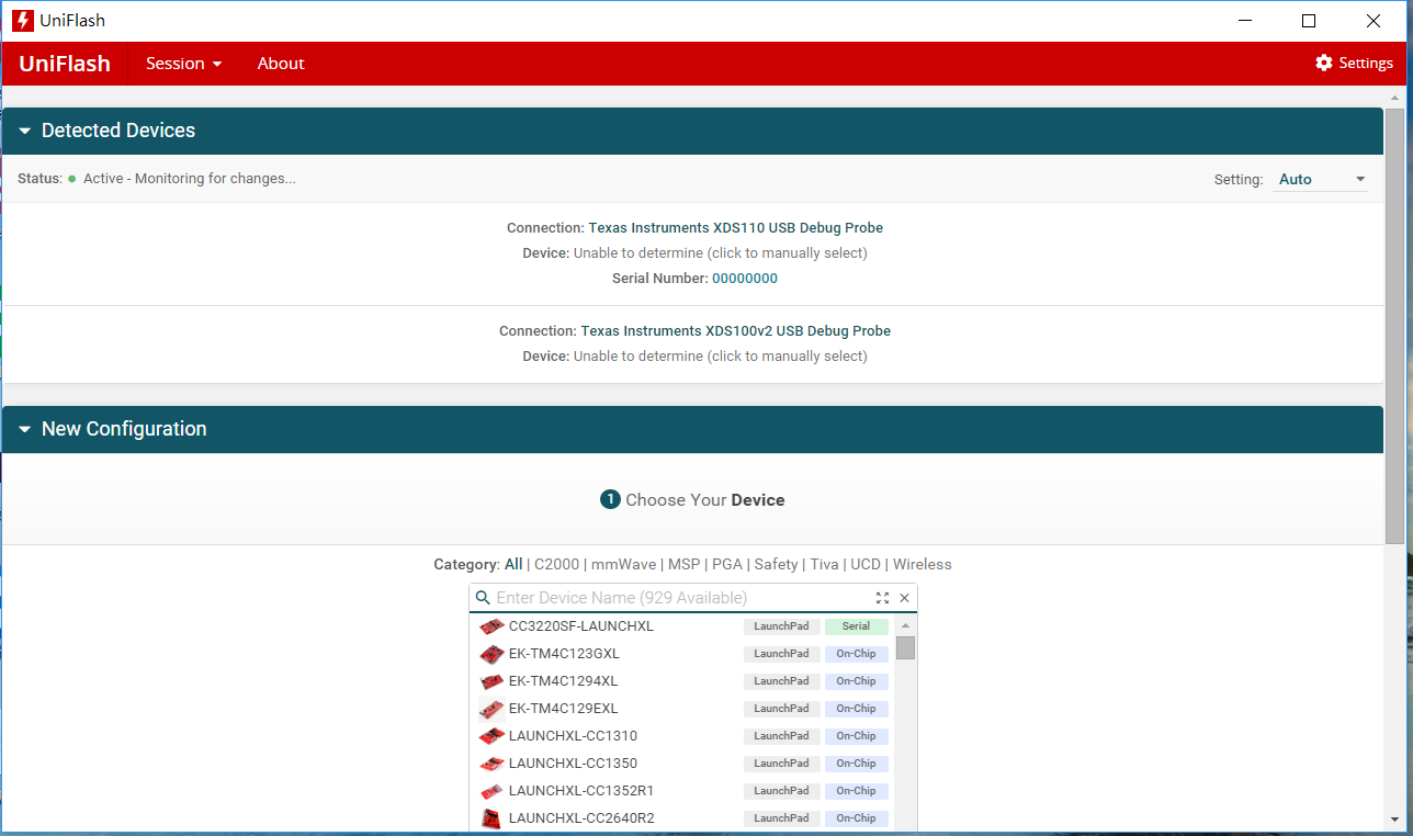
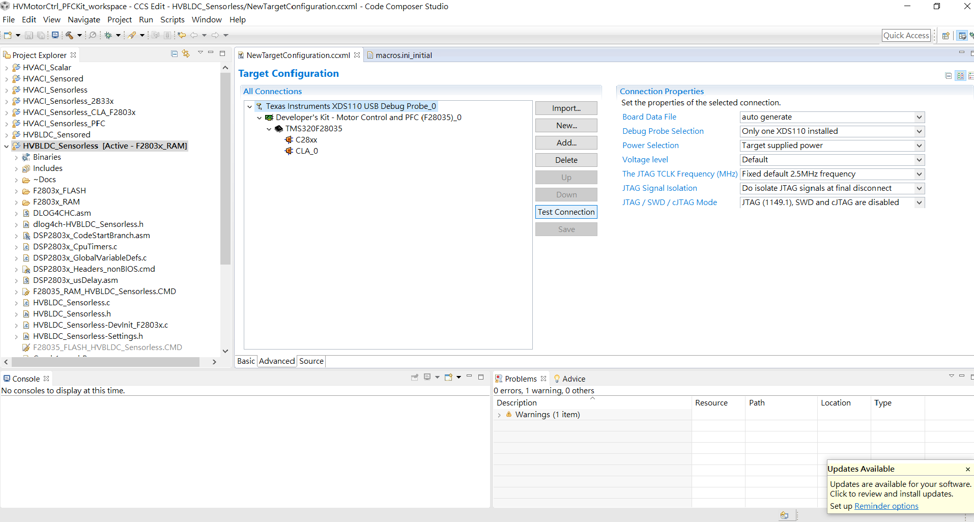
Please help, I just bought XDS110-U a few days ago, and now I can't find my device through CCS or command of xdsdfu -e
as picture below.
I think I accdentally erase its flash program? not sure.
Is there anyway to force reprogram?
Please help, thank you
Yu Hung
Dear Rafael,
Thank you, I will repost here again what I asked in TI contact support email. see ======================== line between.
In case the post is too long to read, here are some summaries
1. My symptom is now not '-233', but '-260', which is Failed to connect XDS110.
2. What I was trying to ask is, what does 'xdsdfu -c' command really do to my XDS110 Debug Probe
because it doesn't say in 'xdsdfu -?' help command.
And, I think because of this 'xdsdfu -c' command, my XDS110 Debug Probe seems dead with '-260' error code.
3. Since I just bought this for about a week, I dont' really think it's USB cable's problem and I dont' have extra one with me now to try.
Is there anything I can try to recover this device (based on '-260' error code and 'xdsdfu -c' unknown command input)?
Or is there any compensation for this from TI?
=====================================================================================
Dear Support,
I just bought this XDS110 Debug Probe and got it for less than a week.
I could detect it at first so I don't think it has anything to do with USB cable and the computer,
but I can't detect it anymore after I did the following,
1. I had diffculties to emulate XDS110 Debug Probe with TMDSHVMTRPFCKIT evaluation board, keep getting the error message like following...
The value is '-233' (0xffffff17).
The title is 'SC_ERR_PATH_BROKEN'.
The explanation is:
The JTAG IR and DR scan-paths cannot circulate bits, they may be broken.
An attempt to scan the JTAG scan-path has failed.
The target's JTAG scan-path appears to be broken
with a stuck-at-ones or stuck-at-zero fault.
2. Becase of the '-233' error I tried varies setting in CCS, and I found the 'xdsdfu' command line program from CCS, see attached picture.
3. So I went to command line and checked with command of 'xdsdfu -?', see the picture below,
4. OK, so to enumerate connected devices, I need to use 'xdsdfu -e', but cause of the resolution, it looks like '-c' to me.
I thought it is an option '-c', so I entered 'xdsdfu -c' and the command reponse me to enter DFU mode,
so I listened and enter DFU mode with command of 'xdsdfu -m' without any doubt, and then entered
'xdsdfu -c'. But then I guess this is where the problem occured!!!
From the xdsdfu help menu, there should be no '-c' option, but 'xdsdfu -c' actually did something to my XDS110 Debug Probe.
I can't detect it anymore with it connected to my notebook, I can't see it on Device Manager, and can't enumerate with 'xdsdfu -e' command!
I think the command might erase the firmware program on the XDS110 Debug Probe.
I just bought this XDS110 Debug Probe, and I think it is broken now by a hidden command in 'xdsdfu' program!!.
Is there any easy way to recover it, if there is, please guide me to resolve it!
Or any local TI supplier in Taiwan can help me to recover my XDS110 Debug Probe,
Hope I can recover it as soon as possible!,
Thank you!
================================================================================================================
Also, for that I can't find my device through CCS or command of xdsdfu -e as picture below.
Please kindly help to solve the problem,
Thank you very much!!
Yu Hung
Dear Rafael,
Yes, I've read the ReadMe.txt at directory C:\ti\ccsv7\ccs_base\common\uscif\xds110, but I don't have spare one with me. I'll try to find one for now....
For recovering from JTAG, got a few questions to make sure,
1. Will another XDS110 Debug Probe with 10-pin adapter do the job?
2. Or I need to get a specific Debug Probe?
3. Should I use the good debug probe with LM FLASH Programmer to reflash the dead XDS110 Debug Probe? or any specific debug probe to pair specific Software Flash programmer?
By the way, the hidden ' -c' option is really not a good idea. It doesn't give any warning but just simply erased my
XDS110 Debug Probe's firmware.
In case I can't find any Debug Probe to reflash my dead XDS110 Debug Probe, what should I do next?
I purchased this through TI Store Website at 2017/07/04 .
Thank you very much for your help!
Yu Hung
Yu Hung,
Yu Hung Cheng said:1. Will another XDS110 Debug Probe with 10-pin adapter do the job?2. Or I need to get a specific Debug Probe?
Any debug probe should be fine for this.
Yu Hung Cheng said:3. Should I use the good debug probe with LM FLASH Programmer to reflash the dead XDS110 Debug Probe? or any specific debug probe to pair specific Software Flash programmer?
The LMFlash programmer does not support the XDS110, but you can use Uniflash or even CCS for that.
Yu Hung Cheng said:By the way, the hidden ' -c' option is really not a good idea. It doesn't give any warning but just simply erased my XDS110 Debug Probe's firmware.
I agree with you and filed an enhancement to add a warning to this and other potentially dangerous hidden options.
Yu Hung Cheng said:In case I can't find any Debug Probe to reflash my dead XDS110 Debug Probe, what should I do next?I purchased this through TI Store Website at 2017/07/04 .
The TI store has a "Help" link that you can use to communicate with them regarding returns. They would be able to provide you with additional details on how to proceed. You can link this thread in communications with them.
I apologize for the inconvenience,
Rafael
Dear Rafael,
You said that in red,
>> 1. Will another XDS110 Debug Probe with 10-pin adapter do the job?>> 2. Or I need to get a specific Debug Probe?
>> Any debug probe should be fine for this.
I am confused! I thought this XDS110 Debug Probe only got 10-pin JTAG pinouts socket like this picture.
You said that any debug probe should be fine for this, but how do you use debug probe with 14-pins JTAG connector to connect to this JTAG with 10-pins pinouts socket.
Could you describe it in more detail with pictures, please? Thank you very much!
And, also,
>> 3. Should I use the good debug probe with LM FLASH Programmer to reflash the dead XDS110 Debug Probe? or any specific debug probe >> to pair specific Software Flash programmer?
>> The LMFlash programmer does not support the XDS110, but you can use Uniflash or even CCS for that.
I mentioned 'LM Flash programmer' is because I read the 'ReadMe.txt' at directory 'C:\ti\ccsv7\ccs_base\common\uscif\xds110' and it says the following...
==================================================================
*** Updating Firmware Using a JTAG Connection. ***
You can update the XDS110 firmware using a JTAG connection. Contact
your vendor for details on how to attache a JTAG cable and for what
programmer tool you should use.
To use the LM Flash Utility from Stellaris:
Make sure to use the option to erase only the required pages of memory.
Flash the boot_loader.bin file to address 0x0000.
Flash the firmware.bin file to address 0x4000.
Power cycle the debug probe (unplug and replug it into the USB port).
===============================================================================
Since the LM Flash programmer is mentioned in the XDS110's ReadMe, why it is not supporting re-program the XDS110's firmware?
Please kindly explain it more. Sorry, I am confused at this as well!.
Thank you!
Yu Hung
Yu Hung,
Please apologize for the delay. Answering your questions:
Yu Hung Cheng said:You said that any debug probe should be fine for this, but how do you use debug probe with 14-pins JTAG connector to connect to this JTAG with 10-pins pinouts socket.
Sorry I wasn't clear. I meant that any debug probe will be logically and electrically suitable to perform this programming - however, you would still need a pin converter from 14 to 10 pin. If you can find a debug probe that has a TI 20-pin connector such as the XDS200, the XDS100v2 or even another XDS110 you can use the existing 20-14 pin adapter supplied with your original XDS110.
Yu Hung Cheng said:Since the LM Flash programmer is mentioned in the XDS110's ReadMe, why it is not supporting re-program the XDS110's firmware?
Sorry again. The LM Flash is mentioned because it is compatible with the device that is built into the XDS110 debug probe (TM4C1294). However, the debug probes supported by this utility to program the TM4C1294 device do not include the XDS110.
One detail: at the very bottom of the Readme.txt file there is a method to try to recover a bricked XDS110 without a JTAG debugger - did you try to do that method?
I didn't test all the steps below myself on a "live" XDS110, but you use Uniflash to do the programming. By going to http://dev.ti.com you can select the device and the debug probe you have connected to your PC:
You can select "settings" and make sure the settings are suitable for the target device (the XDS110 uses a 16MHz crystal) and only necessary pages are erased during download.
Then you can load the files and pass the addresses mentioned in the readme.txt file as shown in the screen below.
After that, click on Load Images and wait for the process to finish.
You will probably need to disconnect and reconnect the newly programmed XDS110 from the USB port for it to be properly recognized.
Hope this helps,
Rafael
Dear Rafael,
Thank you very mcuh for the clear explanation!
>> One detail: at the very bottom of the Readme.txt file there is a method to try to recover a bricked XDS110 without a JTAG debugger - did you try to do that method?
Yes, I've tried to recover a bricked XDS110 without a JTAG debugger by shorting JTAG header's TDO & GND pins, but it doesn't seems to work.
So, I borrowed another XDS110 debug probe to rescue my XDS110 debug probe from someone else.
Like you said, LM Flash does not support XDS110 debug probe, so I tried the UniFlash that you suggested, and successfully loaded 'boot_loader.bin' into my XDS110 debug probe. After that, I can use 'xdsdfu -m' and 'xdsdfu -f firmware.bin -r' commands to flash itself's firmware.bin file. So, now my XDS110 debug probe is back to normal!
Thanks again for your help!
And, now I am facing another problem. Not sure if you can still help me on that.
I am having hard time connecting to TMDSHVMTRPFCKIT with XDS110 debug probe, not sure if you are familiar with TMDSHVMTRPFCKIT.
I have TMDSHVMTRPFCKIT's Isolated XDS100 USB JTAG Emulator connected for the board's M3 section's power source, and the Input for 15VDC power adapter connected to power up the TMS320F28035 ControlCard.See attached picture:
I have UniFlash detected two debug probe, my XDS110 and another one is TMDSHVMTRPFCKIT's onboard USB JTAG emulator XDS100v2, see attached picture.
And, here is my CCS (CCS Version: 7.1.0.00016) setup for the connection, see attached picture.
And, when I press 'Test Connection' button, I receive the following error message.
===============================================================================================================
[Start: Texas Instruments XDS110 USB Debug Probe_0]
Execute the command:
%ccs_base%/common/uscif/dbgjtag -f %boarddatafile% -rv -o -S integrity
[Result]
-----[Print the board config pathname(s)]------------------------------------
C:\Users\user\AppData\Local\TEXASI~1\CCS\
ti\0\0\BrdDat\testBoard.dat
-----[Print the reset-command software log-file]-----------------------------
This utility has selected a 100- or 510-class product.
This utility will load the adapter 'jioxds110.dll'.
The library build date was 'May 2 2017'.
The library build time was '12:59:57'.
The library package version is '6.0.628.1'.
The library component version is '35.35.0.0'.
The controller does not use a programmable FPGA.
The controller has a version number of '5' (0x00000005).
The controller has an insertion length of '0' (0x00000000).
This utility will attempt to reset the controller.
This utility has successfully reset the controller.
-----[Print the reset-command hardware log-file]-----------------------------
The scan-path will be reset by toggling the JTAG TRST signal.
The controller is the XDS110 with USB interface.
The link from controller to target is direct (without cable).
The software is configured for XDS110 features.
The controller cannot monitor the value on the EMU[0] pin.
The controller cannot monitor the value on the EMU[1] pin.
The controller cannot control the timing on output pins.
The controller cannot control the timing on input pins.
The scan-path link-delay has been set to exactly '0' (0x0000).
-----[An error has occurred and this utility has aborted]--------------------
This error is generated by TI's USCIF driver or utilities.
The value is '-233' (0xffffff17).
The title is 'SC_ERR_PATH_BROKEN'.
The explanation is:
The JTAG IR and DR scan-paths cannot circulate bits, they may be broken.
An attempt to scan the JTAG scan-path has failed.
The target's JTAG scan-path appears to be broken
with a stuck-at-ones or stuck-at-zero fault.
[End: Texas Instruments XDS110 USB Debug Probe_0]
==============================================================================================================
Not sure if there is anything wrong with my CCS setup or the board's setup, or if you know where I can find answer for this.
Thank you!
Yu Hung
Yu Hung,
The issue you are seeing now can be caused by the many jumper configurations on your development kit. In the kit I have here (similar to yours but probably an older version) I have to set up jumpers on the M3 module to properly connect using an external JTAG debug probe instead of the built-in XDS100.
Check your kit's Hardware Guide and see if you can find its proper jumper settings - PDFs of these Hardware Guides are supplied with controlSUITE under C:\ti\controlSUITE\development_kits\HVMotorCtrl+PfcKit_<version_of_your_kit>\~Docs
Hope this helps,
Rafeal