Tool/software: Code Composer Studio
Hi.
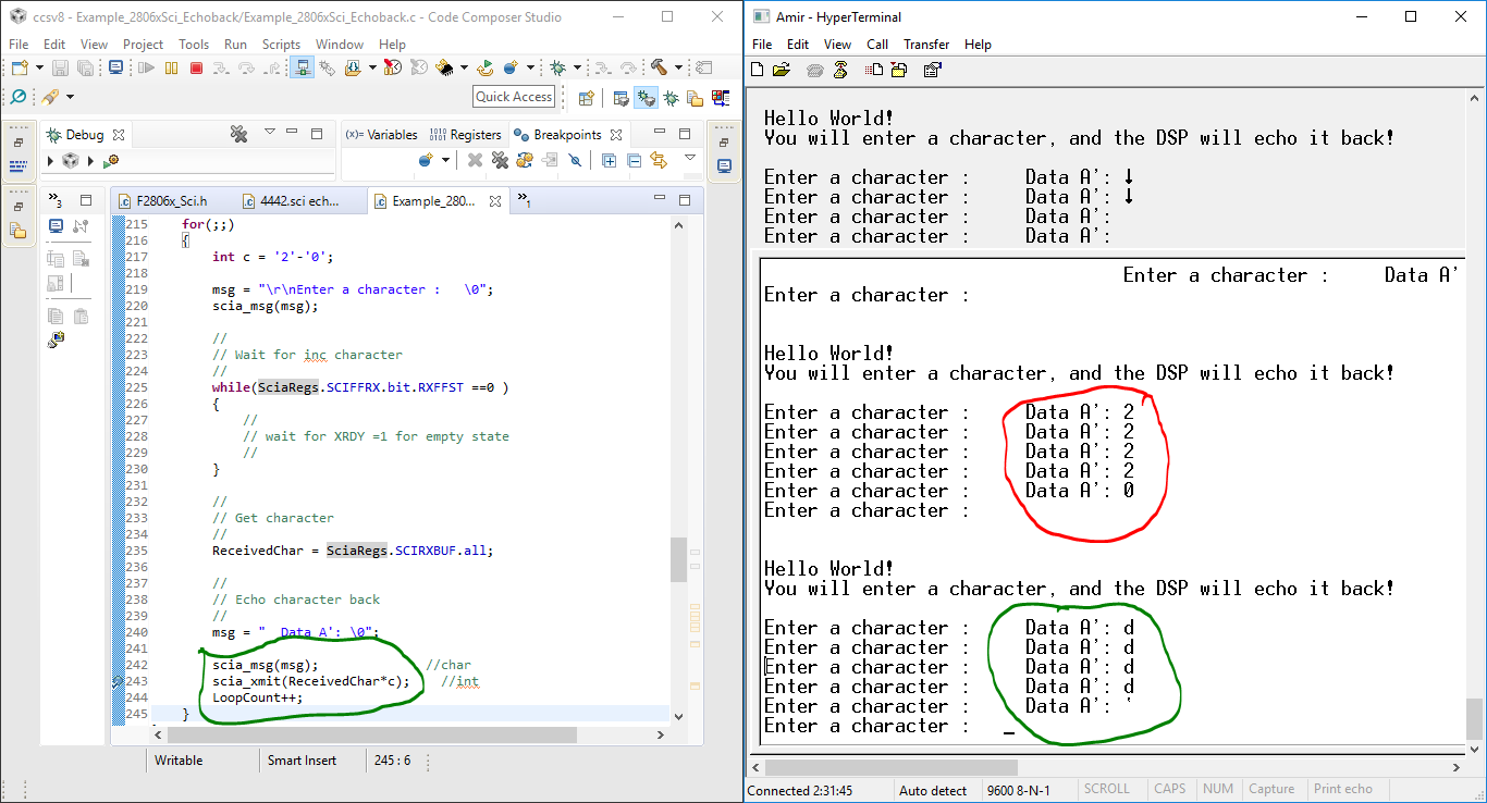
I will send char data from arduino uno using keypad, For example, I send data 15, I want to make an arithmetic program on TI where TI receives the data and share it with 5. I hope the data that appears on PuTTY is 3 (because 15/5) .
What I want to achieve is the number or data that has been received will control the output, such as speed, angle, etc. But, first I want the data sent by Arduino to be calculated on TI and TI can display the results in PuTTY. I use Example code: sci_echoback.
I use the default program and I want to ask which one I need to change to get what I mean as above?
here my ccs code :
//###########################################################################
//
// FILE: Example_2806xScia_Echoback.c
//
// TITLE: SCI Echo Back Example
//
//! \addtogroup f2806x_example_list
//! <h1>SCI Echo Back(sci_echoback)</h1>
//!
//! This test receives and echo-backs data through the SCI-A port.
//!
//! The PC application 'hypterterminal' can be used to view the data
//! from the SCI and to send information to the SCI. Characters received
//! by the SCI port are sent back to the host.
//!
//! \b Running \b the \b Application
//! -# Configure hyperterminal:
//! Use the included hyperterminal configuration file SCI_96.ht.
//! To load this configuration in hyperterminal
//! -# Open hyperterminal
//! -# Go to file->open
//! -# Browse to the location of the project and
//! select the SCI_96.ht file.
//! -# Check the COM port.
//! The configuration file is currently setup for COM1.
//! If this is not correct, disconnect (Call->Disconnect)
//! Open the File-Properties dialog and select the correct COM port.
//! -# Connect hyperterminal Call->Call
//! and then start the 2806x SCI echoback program execution.
//! -# The program will print out a greeting and then ask you to
//! enter a character which it will echo back to hyperterminal.
//!
//! \note If you are unable to open the .ht file, you can create
//! a new one with the following settings
//! - Find correct COM port
//! - Bits per second = 9600
//! - Date Bits = 8
//! - Parity = None
//! - Stop Bits = 1
//! - Hardware Control = None
//!
//! \b Watch \b Variables \n
//! - \b LoopCount, for the number of characters sent
//! - ErrorCount
//!
//! \b External \b Connections \n
//! Connect the SCI-A port to a PC via a transceiver and cable.
//! - GPIO28 is SCI_A-RXD (Connect to Pin3, PC-TX, of serial DB9 cable)
//! - GPIO29 is SCI_A-TXD (Connect to Pin2, PC-RX, of serial DB9 cable)
//
//###########################################################################
// $TI Release: F2806x Support Library v2.04.00.00 $
// $Release Date: Tue Jun 26 03:13:59 CDT 2018 $
// $Copyright:
// Copyright (C) 2009-2018 Texas Instruments Incorporated - http://www.ti.com/
//
// Redistribution and use in source and binary forms, with or without
// modification, are permitted provided that the following conditions
// are met:
//
// Redistributions of source code must retain the above copyright
// notice, this list of conditions and the following disclaimer.
//
// Redistributions in binary form must reproduce the above copyright
// notice, this list of conditions and the following disclaimer in the
// documentation and/or other materials provided with the
// distribution.
//
// Neither the name of Texas Instruments Incorporated nor the names of
// its contributors may be used to endorse or promote products derived
// from this software without specific prior written permission.
//
// THIS SOFTWARE IS PROVIDED BY THE COPYRIGHT HOLDERS AND CONTRIBUTORS
// "AS IS" AND ANY EXPRESS OR IMPLIED WARRANTIES, INCLUDING, BUT NOT
// LIMITED TO, THE IMPLIED WARRANTIES OF MERCHANTABILITY AND FITNESS FOR
// A PARTICULAR PURPOSE ARE DISCLAIMED. IN NO EVENT SHALL THE COPYRIGHT
// OWNER OR CONTRIBUTORS BE LIABLE FOR ANY DIRECT, INDIRECT, INCIDENTAL,
// SPECIAL, EXEMPLARY, OR CONSEQUENTIAL DAMAGES (INCLUDING, BUT NOT
// LIMITED TO, PROCUREMENT OF SUBSTITUTE GOODS OR SERVICES; LOSS OF USE,
// DATA, OR PROFITS; OR BUSINESS INTERRUPTION) HOWEVER CAUSED AND ON ANY
// THEORY OF LIABILITY, WHETHER IN CONTRACT, STRICT LIABILITY, OR TORT
// (INCLUDING NEGLIGENCE OR OTHERWISE) ARISING IN ANY WAY OUT OF THE USE
// OF THIS SOFTWARE, EVEN IF ADVISED OF THE POSSIBILITY OF SUCH DAMAGE.
// $
//###########################################################################
//
// Included Files
//
#include "DSP28x_Project.h" // Device Headerfile and Examples Include File
//
// Function Prototypes
//
void scia_echoback_init(void);
void scia_fifo_init(void);
void scia_xmit(int a);
void scia_msg(char *msg);
//
// Globals
//
Uint16 LoopCount;
Uint16 ErrorCount;
Uint16 ReceivedChar;
//
// Main
//
void main(void)
{
char *msg;
//
// Step 1. Initialize System Control:
// PLL, WatchDog, enable Peripheral Clocks
// This example function is found in the F2806x_SysCtrl.c file.
//
InitSysCtrl();
//
// Step 2. Initalize GPIO:
// This example function is found in the F2806x_Gpio.c file and
// illustrates how to set the GPIO to its default state.
//
//InitGpio(); Skipped for this example
//
// For this example, only init the pins for the SCI-A port.
// This function is found in the F2806x_Sci.c file.
//
InitSciaGpio();
//
// Step 3. Clear all interrupts and initialize PIE vector table:
// Disable CPU interrupts
//
DINT;
//
// Initialize PIE control registers to their default state.
// The default state is all PIE interrupts disabled and flags
// are cleared.
// This function is found in the F2806x_PieCtrl.c file.
//
InitPieCtrl();
//
// Disable CPU interrupts and clear all CPU interrupt flags
//
IER = 0x0000;
IFR = 0x0000;
//
// Initialize the PIE vector table with pointers to the shell Interrupt
// Service Routines (ISR).
// This will populate the entire table, even if the interrupt
// is not used in this example. This is useful for debug purposes.
// The shell ISR routines are found in F2806x_DefaultIsr.c.
// This function is found in F2806x_PieVect.c.
//
InitPieVectTable();
//
// Step 4. Initialize all the Device Peripherals:
// This function is found in F2806x_InitPeripherals.c
//
//InitPeripherals(); // Not required for this example
//
// Step 5. User specific code
//
LoopCount = 0;
ErrorCount = 0;
scia_fifo_init(); // Initialize the SCI FIFO
scia_echoback_init(); // Initalize SCI for echoback
msg = "\r\n\n\nHello World!\0";
scia_msg(msg);
msg = "\r\nYou will enter a character, and the DSP will echo it back! \n\0";
scia_msg(msg);
for(;;)
{
msg = "\r\nEnter a character : \0";
scia_msg(msg);
//
// Wait for inc character
//
while(SciaRegs.SCIFFRX.bit.RXFFST ==0 )
{
//
// wait for XRDY =1 for empty state
//
}
//
// Get character
//
ReceivedChar = SciaRegs.SCIRXBUF.all;
//
// Echo character back
//
msg = " Data A': \0";
scia_msg(msg);
scia_xmit(ReceivedChar);
LoopCount++;
}
}
//
// scia_echoback_init - Test 1,SCIA DLB, 8-bit word, baud rate 0x0103,
// default, 1 STOP bit, no parity
//
void
scia_echoback_init()
{
//
// Note: Clocks were turned on to the SCIA peripheral
// in the InitSysCtrl() function
//
//
// 1 stop bit, No loopback, No parity,8 char bits, async mode,
// idle-line protocol
//
SciaRegs.SCICCR.all =0x0007;
//
// enable TX, RX, internal SCICLK, Disable RX ERR, SLEEP, TXWAKE
//
SciaRegs.SCICTL1.all =0x0003;
SciaRegs.SCICTL2.bit.TXINTENA = 1;
SciaRegs.SCICTL2.bit.RXBKINTENA = 1;
//
// 9600 baud @LSPCLK = 22.5MHz (90 MHz SYSCLK)
//
SciaRegs.SCIHBAUD =0x0001;
SciaRegs.SCILBAUD =0x0024;
SciaRegs.SCICTL1.all =0x0023; // Relinquish SCI from Reset
}
//
// scia_xmit - Transmit a character from the SCI
//
void
scia_xmit(int a)
{
while (SciaRegs.SCIFFTX.bit.TXFFST ==1 )
{
}
SciaRegs.SCITXBUF = a;
}
//
// scia_msg -
//
void
scia_msg(char * msg)
{
int i;
i = 0;
while (msg[i] != '\0')
{
scia_xmit(msg[i]/5);
i++;
}
}
//
// scia_fifo_init - Initalize the SCI FIFO
//
void
scia_fifo_init()
{
SciaRegs.SCIFFTX.all=0xE040;
SciaRegs.SCIFFRX.all=0x2044;
SciaRegs.SCIFFCT.all=0x0;
}
void
Scia_gpio()
{
#if DSP28_SCIA
InitSciaGpio();
#endif // endif DSP28_SCIA
EALLOW;
/* Enable internal pull-up for the selected pins */
// Pull-ups can be enabled or disabled disabled by the user.
// This will enable the pullups for the specified pins.
GpioCtrlRegs.GPAPUD.bit.GPIO28 = 0; // Enable pull-up for GPIO28 (SCIRXDA)
// GpioCtrlRegs.GPAPUD.bit.GPIO7 = 0; // Enable pull-up for GPIO7 (SCIRXDA)
GpioCtrlRegs.GPAPUD.bit.GPIO29 = 0; // Enable pull-up for GPIO29 (SCITXDA)
// GpioCtrlRegs.GPAPUD.bit.GPIO12 = 0; // Enable pull-up for GPIO12 (SCITXDA)
/* Set qualification for selected pins to asynch only */
// Inputs are synchronized to SYSCLKOUT by default.
// This will select asynch (no qualification) for the selected pins.
GpioCtrlRegs.GPAQSEL2.bit.GPIO28 = 3; // Asynch input GPIO28 (SCIRXDA)
// GpioCtrlRegs.GPAQSEL1.bit.GPIO7 = 3; // Asynch input GPIO7 (SCIRXDA)
/* Configure SCI-A pins using GPIO regs*/
// This specifies which of the possible GPIO pins will be SCI functional pins.
GpioCtrlRegs.GPAMUX2.bit.GPIO28 = 1; // Configure GPIO28 for SCIRXDA operation
// GpioCtrlRegs.GPAMUX1.bit.GPIO7 = 2; // Configure GPIO7 for SCIRXDA operation
GpioCtrlRegs.GPAMUX2.bit.GPIO29 = 1; // Configure GPIO29 for SCITXDA operation
// GpioCtrlRegs.GPAMUX1.bit.GPIO12 = 2; // Configure GPIO12 for SCITXDA operation
EDIS;
}
//#endif
//===========================================================================
// No more.
//===========================================================================
//
// End of File
//
and this below is my Arduino program :
#include <Keypad.h>
#include <LiquidCrystal.h>
#include <Wire.h>
const byte ROWS = 4;
const byte COLS = 4;
char keys[ROWS][COLS] =
{
{'1','2','3','A'},
{'4','5','6','B'},
{'7','8','9','C'},
{'*','0','#','D'}
};
byte rowPins[ROWS] = {A2,A3,A4,A5}; //connect to the row pinouts of the keypad
byte colPins[COLS] = {11,10,9,8}; //connect to the column pinouts of the keypad
Keypad keypad = Keypad( makeKeymap(keys), rowPins, colPins, ROWS, COLS );
String textFromSerial = "";
boolean stringComplete = false ; // whether the string is complete
const int maxDigits = 6;
char UL[6];
int k=0;
long dtKey;
char key;
int a = ('0'-48);
// initialize the library with the numbers of the interface pins
LiquidCrystal lcd (2,3,4,5,6,7);
void (* resetki) (void)=0; //---------------------PROG RESET-------------------------------------
void setup()
{
Serial.begin(9600);
// set up the LCD's number of columns and rows:
lcd.begin(16,2);
// set the cursor to column 0, line 0
// (note: line 0 is the first row, since counting begins with 0):
displayMenu();
}
void displayMenu()
{
lcd.setCursor(0, 0);
lcd.print("'COR'-Enter Data");
lcd.setCursor(0, 1);
lcd.print("'CAN'-Reset");
}
void serialEvent() //------------------------------------BACA DATA SERIAL ------------------------------------
{
while (Serial.available()>0)
{
lcd.clear();
key = keypad.getKey();
// get the new byte:
char data = Serial.read () ;
// add it to the textFromSerial:
if (data== '\n')
{
lcd.setCursor(0,0);
lcd.print("Data A : ");
//lcd.print(key);
//Serial.print(key);
lcd.setCursor(0,1);
lcd.print("Data A': ");
lcd.print(textFromSerial);
//textFromSerial = "";
}
else
{
if(data!='\r')
{
textFromSerial += data;
}
}
}
}
/*
void baca()
{
dtKey = dtKey*10+key;
dtKey = analogRead(key)/4;
EEPROM.write(addr, dtKey);
address = addr;
value = EEPROM.read(address);
Serial.print("Data A : ");
Serial.print("\t");
Serial.print(value);
Serial.println();
address = address + 1;
if (address == 512)
address=0;
addr = addr+1;
if (addr == 512);
addr = 0;
delay(500);
}
*/
void enter () //---------------------------------ENTER---------------------------------------------
{
key = keypad.getKey();
dtKey = dtKey*10+(key-a);
String send_data;
send_data = String (dtKey);
//Serial.print("Data A : ");
// Serial.print("\t");
Serial.print(send_data);
Serial.print("\t");
Serial.println();
//Serial.print("Data A': ");
//Serial.print("\t");
Serial.print(textFromSerial);
//Serial.println();
lcd.clear();
lcd.setCursor(0,0);
lcd.print(" Data Sent ");
delay(3000);
resetki();
}
int GetNumber() //-----------------------GET NUMBER-------------------------------------
{
key = keypad.getKey();
switch(key)
{
case 'A': // ----------------------INPUT DATA------------------------------
lcd.clear();
lcd.setCursor(0, 0);
lcd.print("Data A : ");
lcd.setCursor(0, 1);
lcd.print("Data A': ");
lcd.setCursor(9, 0);
while (k<6)
{
key = keypad.getKey();
if (key)
{
// Print a message to the LCD.
dtKey = dtKey * 10 + (key - '0');
lcd.print(key);
UL[k] = key;
k++;
}
}
break;
case 'C': //--------------------------CLEAR DATA---------------------------------------------
lcd.clear();
lcd.setCursor(0,0);
lcd.print("Data A : ");
lcd.setCursor(9, 0);
lcd.setCursor(0, 1);
lcd.print("Data A': ");
while (k=0)
{
//char key = keypad.getKey();
if (key)
{
lcd.print(0x7f);
UL[k] = 0;
k--;
}
break;
case '*':
resetki(); //------------------------------RESET--------------------------------------------
break;
case 'D':
dtKey=0;
break;
case 'B':
displayMenu();//---------------------------MENU-------------------------------------------
break;
case '#':
enter(); //--------------------------------ENTER-------------------------------------------
break;
}
}
}
void loop() //---------------------------- VOID LOOP -------------------------------------
{
GetNumber();
serialEvent();
}
I have tried my best but still haven't got the solution. So, I really hope for friends and experts to share a bit of your knowledge. Please guide me.
Regards
Amir