Tool/software: Code Composer Studio
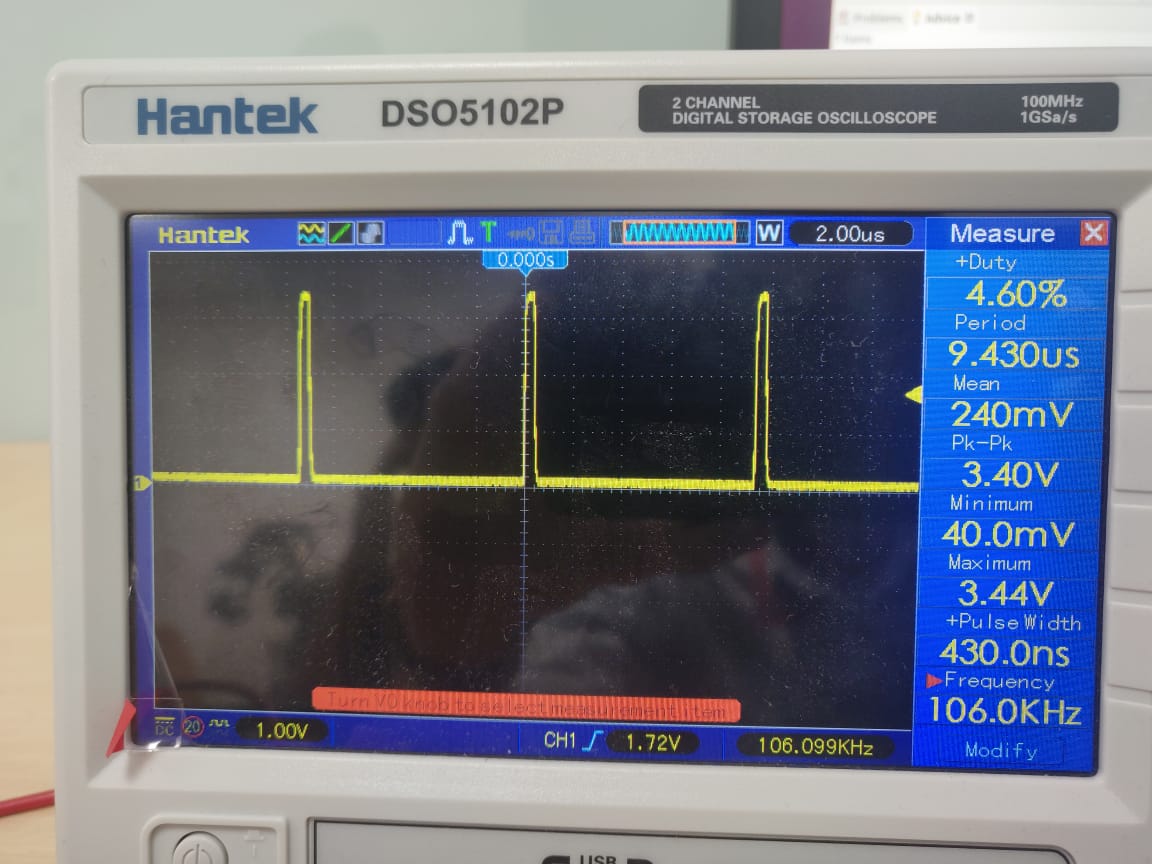
I am trying SSI communication with TM4C123GXL and Arduino Uno. I am using TM4C123GXL as Master and Arduino Uno as Slave and I want to read data sent by slave. But on configuring the master (SSI0) I am getting 1MHz CLK and CS pin is also working fine(Refer Picture Clock and Chip Select). While on Tx pin of Tiva Board There is some issue.(Refer Picture TX Tiva). I want to receive data from UNO using SSI. My main goal is to interface LS7366R Encoder Buffer with TM4C123GXL which works on SPI. So can anyone help on this. I am attaching pictures of oscilloscope.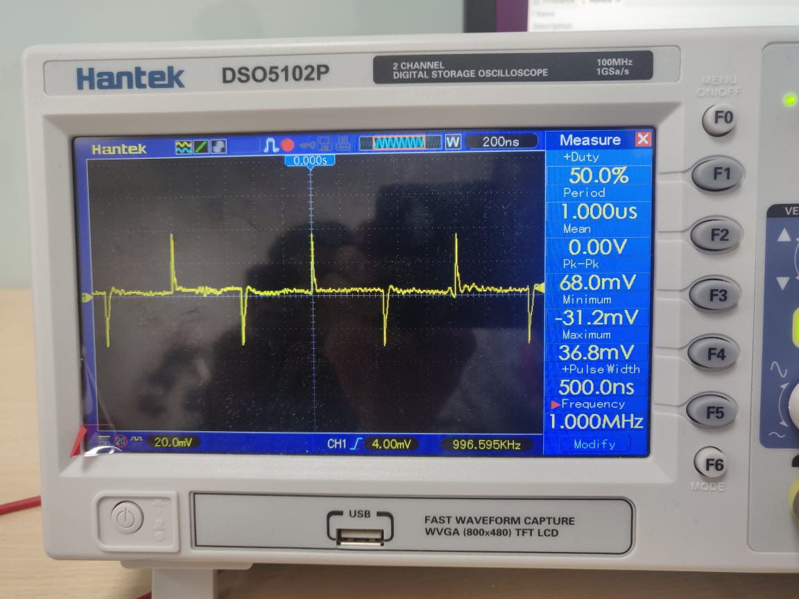
#include <stdbool.h>
#include <stdint.h>
#include "inc/hw_memmap.h"
#include "inc/hw_types.h"
#include "inc/hw_gpio.h"
#include "driverlib/gpio.h"
#include "driverlib/pin_map.h"
#include "driverlib/rom.h"
#include "driverlib/sysctl.h"
#include "driverlib/uart.h"
#include "driverlib/flash.h"
#include "driverlib/adc.h"
#include "driverlib/ssi.h"
#include "driverlib/buttons.h"
#include "utils/uartstdio.h"

#define OFF 0x00
#define RED 0x02
#define BLUE 0x04
#define GREEN 0x08

/******************************************************************************
 * Configure the UART and its pins.  This must be called before UARTprintf(). *
 ******************************************************************************/
void ConfigureUART(void)
{
    // Enable the GPIO Peripheral used by the UART.
    ROM_SysCtlPeripheralEnable(SYSCTL_PERIPH_GPIOA);

    // Enable UART0
    ROM_SysCtlPeripheralEnable(SYSCTL_PERIPH_UART0);

    // Configure GPIO Pins for UART mode.
    ROM_GPIOPinConfigure(GPIO_PA0_U0RX);
    ROM_GPIOPinConfigure(GPIO_PA1_U0TX);
    ROM_GPIOPinTypeUART(GPIO_PORTA_BASE, GPIO_PIN_0 | GPIO_PIN_1);

    // Use the internal 16MHz oscillator as the UART clock source.
    UARTClockSourceSet(UART0_BASE, UART_CLOCK_PIOSC);

    // Initialize the UART for console I/O.
    UARTStdioConfig(0, 115200, 16000000);
}

/******************************************************************************
 * Configure the onboard LED.  This must be called before changing LED state. *
 ******************************************************************************/
void ConfigureLED(void)
{
	// Configure on-board LED and turn it off
	// First, enable the peripheral
	SysCtlPeripheralEnable(SYSCTL_PERIPH_GPIOF);

	// Define output to the 3 possible colors as they are bound to 3 different pins
	GPIOPinTypeGPIOOutput(GPIO_PORTF_BASE, GPIO_PIN_1 | GPIO_PIN_2 | GPIO_PIN_3);
	// Write binary output to these 3 pins
	GPIOPinWrite(GPIO_PORTF_BASE, GPIO_PIN_1 | GPIO_PIN_2 | GPIO_PIN_3, OFF);

	// It just wait a little bit (looping)
	SysCtlDelay(20000000);
}

/***************************************
 * Main function, program entry point. *
 ***************************************/
int main(void)
{

     uint32_t ui32Message = 0;

    // Set the clocking to run at 50 MHz from the PLL.
    ROM_SysCtlClockSet(SYSCTL_SYSDIV_2_5| SYSCTL_USE_PLL | SYSCTL_XTAL_16MHZ |
                       SYSCTL_OSC_MAIN);

    // Initialize the onboard LED
    ConfigureLED();

    SysCtlPeripheralEnable(SYSCTL_PERIPH_SSI0);

    SysCtlPeripheralEnable(SYSCTL_PERIPH_SSI0);
    SysCtlPeripheralEnable(SYSCTL_PERIPH_GPIOA);
    GPIOPinConfigure(GPIO_PA2_SSI0CLK);
    GPIOPinConfigure(GPIO_PA3_SSI0FSS);
    GPIOPinConfigure(GPIO_PA4_SSI0RX);
    GPIOPinConfigure(GPIO_PA5_SSI0TX);
    GPIOPinTypeSSI(GPIO_PORTA_BASE, GPIO_PIN_4 | GPIO_PIN_3 | GPIO_PIN_2);

    SSIConfigSetExpClk(SSI0_BASE, SysCtlClockGet(), SSI_FRF_MOTO_MODE_0, SSI_MODE_MASTER, 1000000, 8);
    SSIEnable(SSI0_BASE);
    SSIIntEnable(SSI0_BASE, SSI_RXFF);
    // Initialize the UART and configure it
    ConfigureUART();

    while(1)
    {
        SSIDataPut(SSI0_BASE,0x0F);

    	SSIDataGet(SSI0_BASE, &ui32Message);
    	if(ui32Message !=0){
    	    UARTprintf("'%c' ", ui32Message);
    	}
    	while(SSIBusy(SSI0_BASE));
    }
}