This thread has been locked.

If you have a related question, please click the "Ask a related question" button in the top right corner. The newly created question will be automatically linked to this question.

CCS/TMS320C5535: Program works when flashed from debugger, but not when flashed from an EEPROM

Part Number: TMS320C5535

Tool/software: Code Composer Studio

I'm developing on a TMS320C5535 using the XDS110 debugger, the C5000 chip support library, and Code Composer version:  8.3.0.00009. I have a program that uses GPT0 in the C5535 to blink an LED every second indefinitely. When I flash this program using the debugger, not issues occur and the LED happily blinks forever. 

However, when I burn the boot image of the program onto a 512kb I2C EEPROM and then have the C5535 boot from it, the C5535 hangs. The LED blinks correctly 3 times, and then it goes solid red. The C5535 successfully starts up after reading the boot image from the EEPROM, so I don't think it's I2C communication issue.

I already used the I2C EEPROM programmer to check that the data in the EEPROM memory and the .bin file matches. They do match, so there's no problem there.

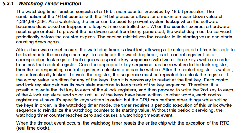
Perhaps the way I formatted the boot image is incorrect? 

Here are my specs:


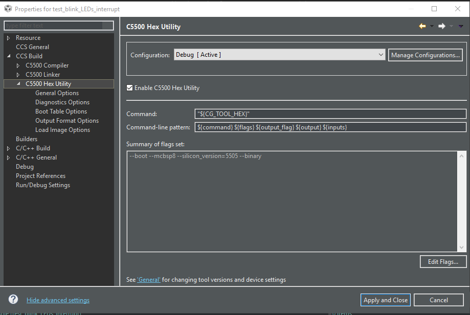
**** Build of configuration Debug for project test_blink_LEDs_interrupt ****

"C:\\ti\\ccsv8\\utils\\bin\\gmake" -k -j 12 all -O 
 
Building file: "../main.c"
Invoking: C5500 Compiler
"C:/ti/ccsv8/tools/compiler/c5500_4.4.1/bin/cl55" -v5515 --memory_model=large -g --include_path="C:/ti/c55_lp/c55_csl_3.08/inc" --include_path="C:/Users/Inno Algo/Desktop/puck_workspace/test_blink_LEDs_interrupt" --include_path="C:/ti/ccsv8/tools/compiler/c5500_4.4.1/include" --define=c5535 --display_error_number --diag_warning=225 --ptrdiff_size=16 --preproc_with_compile --preproc_dependency="main.d_raw"  "../main.c"
Finished building: "../main.c"
 
Building target: "test_blink_LEDs_interrupt.out"
Invoking: C5500 Linker
"C:/ti/ccsv8/tools/compiler/c5500_4.4.1/bin/cl55" -v5515 --memory_model=large -g --define=c5535 --display_error_number --diag_warning=225 --ptrdiff_size=16 -z -m"test_blink_LEDs_interrupt.map" --stack_size=0x200 --heap_size=0x400 -i"C:/ti/ccsv8/tools/compiler/c5500_4.4.1/lib" -i"C:/ti/ccsv8/tools/compiler/c5500_4.4.1/include" -i"C:/Users/Inno Algo/Desktop/puck_workspace/C55XXCSL_LP" --reread_libs --display_error_number --warn_sections --xml_link_info="test_blink_LEDs_interrupt_linkInfo.xml" --rom_model --sys_stacksize=0x200 -o "test_blink_LEDs_interrupt.out" "./main.obj" "../C5535.cmd"  -l"C:/ti/c55_lp/c55_csl_3.08/ccs_v6.x_examples/C55XXCSL_LP/Debug/C55XXCSL_LP.lib" -llibc.a 
<Linking>
Finished building target: "test_blink_LEDs_interrupt.out"
 
Building files: "test_blink_LEDs_interrupt.out"
Invoking: C5500 Hex Utility
"C:/ti/ccsv8/tools/compiler/c5500_4.4.1/bin/hex55" --boot --mcbsp8 --silicon_version=5505 --binary -o "test_blink_LEDs_interrupt.bin"  "test_blink_LEDs_interrupt.out" 
Translating to Binary format...
   "test_blink_LEDs_interrupt.out"   ==> .cinit 	(BOOT LOAD)
   "test_blink_LEDs_interrupt.out"   ==> vectors 	(BOOT LOAD)
   "test_blink_LEDs_interrupt.out"   ==> .text 	(BOOT LOAD)
   "test_blink_LEDs_interrupt.out"   ==> .switch 	(BOOT LOAD)
Finished building: "test_blink_LEDs_interrupt.out"
 

**** Build Finished ****

Here are the .bin, .map., and .cmd files of the program I'm booting from: test_blink_LEDs_interrupt.zip

Any help or guidance would be greatly appreciated! 

NOTE: Before making any suggestions, please go through the original thread. I tried many different potential solutions and also documented any observations that will potentially be helpful.

Best, 

Eddie

  • To whom it may concern,

    UPDATE:
    I just tried booting up the DSP using UART instead of the I2C EEPROM and the same issue persists. What I conclude from this is that there must be something not formatted correctly in the .bin file itself because the same issue happens regardless of booting the DSP from EEPROM or from UART.

    Best,
    Eddie
  • Hi Eddie,
    I assume you are loading a *.out file with the CCS debugger. Can you then extract the contents of memory to a *.bin file on your host machine (you can do this using the "Save Memory" feature of the "Memory Browser" view) and compare it to the *.bin file that you are flashing to EEPROM?

    Thanks
    ki
  • Ki,

    Sure, I can try that!

    Can you please specify which memory page I should extract? (DATA, PROGRAM, IO). Memory browser is forcing me to save them individually. I'm assuming that the start address would be 0x000000, but I'm unsure the length in words I should extract after that address.  

    I'm using SPRS737C (6.2.2) as a reference but am still unsure which memory sections I'm actually trying extract and convert into a .bin 

    After extracting and converting the .out to a .bin, should I try to boot the processor from it to see if there's a difference in behavior? 

    Best, 

    Eddie 

  • Hi Eddie,
    Sorry for the delayed response. We have had a lot of internal discussion on how to investigate this as there are multiple variables. I think comparing the memory dumps between the working and non-working environments is still a good start.

    In both cases, please have the debugger environment so that the program is at the same proper system start location. Then dump the following program (page 0) memory ranges:

    -DARAM0 - Start Address: 0xC0, Length: 0x1F40 (bytes)
    -DARAM4 - Start Address: 0x8000, Length: 0x2000 (bytes)
    -DARAM5 - Start Address: 0xA000, Length: 0x2000 (bytes)
    -SARAM0 to SARAM04 - Start Address: 0x10000, Length: 0x10000 (bytes)
    -SARAM31 - Start Address: 0x4E000, Length: 0x2000 (bytes)

    Make sure you name them to indicate which dump is from the working environment (loaded by debugger) and which dump is from the failing (boot from EEPROM) environment.

    Thanks
    ki
  • Ki, 

    I started debug mode and let the program halt at main() without pressing the start button. I extracted the memory ranges you requested using memory viewer and can find them here: Debugger Program Mem Dump.zip

    As for the EEPROM/UART dump, I was unsure what exactly you were asking for since I'd still be debugging the same program as above. So I took all the important output files that HEX55 outputs, since the .bin file is what I'm using as the boot image for the EEPROM/UART. 

    For reference, you can see what memory sections get filled below. All sections after SARAM4 are unfilled: 

    Please let me know if there's any more data or information you need. 

    Best, 

    Eddie

  • Eddie Carrera said:
    As for the EEPROM/UART dump, I was unsure what exactly you were asking for since I'd still be debugging the same program as above. So I took all the important output files that HEX55 outputs, since the .bin file is what I'm using as the boot image for the EEPROM/UART. You can find the files here: (Please visit the site to view this file)

    I'm actually looking for the same contents of memory at the same time as what you did when loading in CCS:

    Eddie Carrera said:
    I started debug mode and let the program halt at main() without pressing the start button.

    Basically at the start of main,

    Please send those dumps.

    Thanks

    ki

  • Ki, 

    I connected both the debugger and the EEPROM to the custom board. Then I powered on the board and waited a few seconds to make sure that the C5535 had enough time to boot from the EEPROM through I2c. After a few seconds I pressed the Debug button and extracted the memory contents that you asked for: 6746.Boot Image (EEPROM) Mem Dump.zip

    Please let me know if you think I made an error in my steps I described above. 

    Best, 

    Eddie

  • Eddie Carrera said:
    After a few seconds I pressed the Debug button

    Do you mean the little "bug" icon which launches a debug session? That would reload the program via CCS.

    What we are looking for is to do a comparison of memory contents between when CCS load the program, and when the program is loaded from EEPROM. The point in the application where we want to do this is basically where you feel is the "system start point" of the application. When loaded by CCS, you can run to that point manually and do the dump. When loaded via EEPROM, you need to have the program halt at that same location and then attach the debugger to it via a "manual launch", which will simply establish connection to the target without loading anything. Depending on the contents of your startup GEL file, you may not want to use one at all in this case. This is to avoid any initialization actions that can mess up with the target state. We basically want to connect to the target with as little intrusion as possible and then dump the contents of memory. The trick is to find a way where the code is halted at the start point for the case where it is loaded from EEPROM. I don't have a good suggestion. Perhaps an embedded breakpoint or some hook in the code needs to be added.

  • Ki, 

    Thank you for the detailed explanation, I had no idea that the debugger could connect to the target without loading the program first (manual launch) so thanks for bringing that up! 

    I haven't used any .GEL files during development, so all the initialization will be done directly from the code. I opted to add a while(1); at the beginning of main() to ensure that the program hangs there and I loaded the new program with that change onto the EEPROM. 

    I followed similar steps as before, but this time with a manual launch instead of pressing the "bug" icon as I did before. 

    After manually launching the debugger, I entered into CCS debug mode and saw that the device was disconnected: 

    I right clicked the probe row and connected it, but then the probe was immediately suspended:


    I clicked on the "Resume" icon and then clicked on the "Suspend" icon. My assumption at this point is that the program is in that while(1); loop I added at the start of main(). At this point I went into memory browser and extracted the memory contents you asked for:  

    Boot Image (EEPROM) Mem Dump Manual Launch.zip

    Best, 

    Eddie

  • Eddie Carrera said:
    I opted to add a while(1); at the beginning of main() to ensure that the program hangs there and I loaded the new program with that change onto the EEPROM. 

    Cool, this will do.

    Eddie Carrera said:
    I clicked on the "Resume" icon and then clicked on the "Suspend" icon. My assumption at this point is that the program is in that while(1); loop I added at the start of main()

    yes, me too. You can try just loading the debug symbols to make sure where you are halted

    Eddie Carrera said:
    At this point I went into memory browser and extracted the memory contents you asked for:  

    great, thanks. One last thing we would need is the memory dump from when the code is loaded voa CCS debugger. The last set of dumps for that you set do not have the while(1) I assume.

    One other thing - can you provide dumps for both environments in binary format instead of TI dat? Thanks

    ki 

  • Ki,

    Ask and you shall receive: 

    Debugger dump: 2450.Debugger mem dump with while(1).zip 

    Boot image (EEPROM) dump: 5226.Boot image (EEPROM) mem dump with while(1).zip

    Binary file that was loaded onto the EEPROM:  test_blink_LEDs_interrupt.zip

    Please let me know if there's anything else I can help you with. I have been developing code for the C5535 for a few months now and have been able to resolve most issues that came up with it over time, but this bootloading issue is something I just haven't been able to figure out. 

    Best, 

    Eddie

  • Thanks Eddie. The memory contents between the two environments are certainly different as suspected. This is a difficult issue to debug. There are a lot of potential areas that could be the root cause. I know that you posted in the device forum and received a response that it could be an issue with the the tools by referencing some older forum posts.

    https://e2e.ti.com/support/processors/f/791/p/785271/2934530#2934530

    But the end result of those older posts turned out to be an issue with the user's environment and not the tools:

    https://e2e.ti.com/support/tools/ccs/f/81/p/417942/1490144#1490144

    Hence I do not suspect that it is a tools issue. It is likely some environment issue. Note the differences in environment between one where CCS loads the program and another where it is loaded from EEPROM. Is the CCS GEL file doing any initialization that is not being done when the program is loaded from EEPROM? It is something I feel the device experts can help more on. I'll bring this back to the attention of the device experts (sorry for the constant back and forth).

    ki

  • Ki,

    Thank you for working through this problem. Luckily I'm still able to develop on the C5535 with the debugger, so my application development can proceed. Obviously this issue will have to be resolved eventually since users can't be expected to load the program themselves using a debugger.

    I don't include a .gel when I flash using debugger since all the initialization is done in the code itself.

    Should I start another thread or will the device experts continue on this one?

    Again, I appreciate the help so far.

    Best,
    Eddie
  • I've reassigned this thread back to the device experts so they should see it and pick it up.

    Thanks for your patience on all of this.
  • It's been a week since this this case has been reassigned and I have not heard back from anyone, I'm just following up. 

  • Hello Eddie,
    I see this issue comes back to us again.
    Okay let's first check what can be the reason to hang from software point of view.
    When you have standalone program and it crashes that means it has some bug in it. But in this case it works when loaded from the debugger. So the first thing that comes to mind for me is the watchdog timer. In stand alone program it is working on its own while when connected to debugger it is suppressed.
    Can you check please in what configuration is WDOG in your program? Is it initialized and maintained at all?
    Thanks
    Michail
  • Michail, 

    It seems to me that the watchdog is disabled by default on device start-up and I would have to actively set registers up to enable it, which I do not do at all in the code.  

    This product is still under development and I want to consider booting the device from SPI flash now. The reason I decided to boot from I2C EEPROM was because the I2C lines can be shared between the C5535, the I2C EEPROM, and the I2C EEPROM programmer. I did not think this similar setup would be possible with SPI flash memory IC. 

    After doing a bit more research I see now that it is possible (I'm still a young engineer!):

    Would a setup like this work for the C5535? Do you have any suggestions or reference schematics for SPI flash in-circuit programming circuity? I will refer to SPRABL7D for proper implementation but would like to know if there's any other details I should know.  

    Best, 

    Eddie

  • Michail,

    I would also like to follow up with another detail:

    I already tried booting up the DSP using UART instead of the I2C EEPROM using the same boot image, but the same issue persists. The LED blinks 8 times before it stops. When the program is ran through the debugger the LED blinks indefinitely (which is what is suppose to happen). What I conclude from this is that there must be something not formatted correctly in the .bin file itself because the same issue happens regardless of booting the DSP from EEPROM or from UART.

    I want to try using booting the DSP from a SPI flash because this issue has been going on for awhile and I want to try something new to resolve it. However, I'm worried that booting from a SPI flash will still not work because if the boot image isn't working for I2C or UART, why would it work with SPI flash?

    Would you recommend that I keep trying to figure this issue out using I2C and UART? or would you recommend spending resources to try to boot using SPI flash?

    Best,
    Eddie

  • Eddie,
    you can try booting the device from SPI flash. It is always good to try another way which will eventually resolve the issue.
    It is correct that I2C lines can be shared between the C5535, EEPROM and programmer but in case of SPI situation is different.
    Hardware setup on the picture has many mistakes and can even damage the C5535.
    - diode on supply line will not help at all, you will still feed the DSP with supply through data lines of the programmer and internal protection diodes on C5535 ports.
    - serial resistors are with low resistance and already supplied DSP output pins will confront with programmer ones producing high currents out of specs which can lead to damage either in C5535 or programmer unit.

    The right way to go is to completely disconnect the SPI EEPROM chip during programming.

    Michail
  • Michail,

    Thank you for your suggestion. I will use shunt jumpers to connect/disconnect the traces like you've mentioned.

    But that still leaves my other question:

    I'm worried that booting from a SPI flash will still not work because the boot image isn't working for I2C or UART. If the same problem (LED stops blinking after 8 times) happens with I2C and UART, wouldn't the same thing happen for SPI? The only thing that changes is the communication protocol (I2C/UART/SPI), but the boot image stays the same, so I'm assuming that the same problem will persists. Do you still think it's worth the effort to acquire a SPI flash programmer to try booting from flash?

    Currently, I believe that the boot image formatting is what's causing the issue because when I change the linker command file, the behavior of the LED changes.  

    Best, 

    Eddie

  • Eddie,
    you are right that there is a big chance this issue will persist also with SPI flash setup. Although (if it is not so big effort) this test will prove that produced image is not correct if the behaviour is the same. SPI NOR flash boot is a classic way for loading customer program to these DSP and is proven to work on many devices both in production and development. According to this it will be a good test in case there is a bootloader bug which appears in your specific case with I2C/UART boot. It is not needed to make complex hardware setup with programmer connected do dev board. I think just a few tests will be enough with fly-wire connections and a socket for the chip so it can be removed and put to appropriate programmer outside. Even just one test will be enough if there are not other issues and DSP boots successfully.

    BR
    Michail
  • Michail,

    Thank you for your feedback. After talking to the rest of the engineering team we will order the SPI programmer and give this suggestion a try. 

    However, we still do not think that with will solve the problem because we believe its a boot image problem. While we wait for the SPI programmer, are there any other suggestions for resolving this issue? 

    You mentioned that it might be the watchdog timer, but that is never initiated/maintained in the code and it is off by default, so I don't believe that's the issue. 

    Best, 

    Eddie

  • Eddie,
    in the meantime I can suggest to make changes in the software and test.
    For example do not use interrupts - make blinking LED's by making delays and toggle pins directly in main().
    Also minimize stack usage - try to use less functions and subroutines.
    Logging changes of behaviour, if any, will be helpful afterwards.

    BR
    Michail
  • Eddie Carrera said:
    I'm worried that booting from a SPI flash will still not work because the boot image isn't working for I2C or UART. If the same problem (LED stops blinking after 8 times) happens with I2C and UART, wouldn't the same thing happen for SPI?

    Using a EZDSP5535 I can repeat the failure when loading test_blink_LEDs_interrupt.bin from your first post over UART, although on some attempts the LED stops flashing after 4 to 7 times. The EZDSP5535 was configured with SW3:1 Off, SW3:2 On, SW3:3 Off and SW3:4 On which enables the UART connection and disables boot from the on board SPI flash device.

    I connected to the TMS320C5535 with the on-board XDS100v2 before loading the program over the UART, with no GEL file specified in the target configuration file so the debugger is not attempting to configure the device.

    If the program is halted while the LED is still flashing then the WDT is shown as disabled (WDEN reads as zero). I.e. the watchdog doesn't appear to be the problem.

    If the program is halted after the LED has stopped flashing the debugger reports the following error:

    C55xx: Trouble Halting Target CPU: (Error -2130 @ 0x400) Unable to access device memory. Verify that the memory address is in valid memory. If error persists, confirm configuration, power-cycle board, and/or try more reliable JTAG settings (e.g. lower TCLK). (Emulation package 8.1.0.00012)

    After this the debugger is reporting the core registers as:

    PC 0x011128 Program Counter [Core]
    XSP 0x000154 Extended data stack pointer [Core]
    XSSP 0x00025D Extended system stack pointer [Core]
    LCRPC 0x0114A4 Return address register [Core]

    Where the same register values have been seen on multiple times, meaning the crash appears to happen at the same place each time.

    From the map file attached to your first post the PC is in _GPT_getCnt and the LCRPC is in main. From the disassembly the return address is for the instruction after CALL #0x0110fe (_GPT_getCnt in the map file) so the return address is valid.

    Does this help in narrowing down the cause of the problem?

  • Eddie Carrera said:
    I'm worried that booting from a SPI flash will still not work because the boot image isn't working for I2C or UART. If the same problem (LED stops blinking after 8 times) happens with I2C and UART, wouldn't the same thing happen for SPI?

    Some more tests with a TMDX5535EZDSP showed:

    a. The test_blink_LEDs_interrupt.bin from your original post fails when booted from UART or SPI flash.

    b. The bootimg1.bin from the Spectrum Digital boot post example works when booted from UART or SPI flash.

    I.e. does appear to be a problem with the test_blink_LEDs_interrupt.bin boot image, rather than the boot source.

  • Eddie Carrera said:
    I have a program that uses GPT0 in the C5535 to blink an LED every second indefinitely.

    Can you show how the program calls GPT_Open and GPT_getCnt in the c55xx_csl?

    From debugging I found the crash happens when GPT_getCnt is called and the hGpt->regs field has a corrupt value of 0xF000 rather than the address for for CSL_TIM_0_REGS (0x1810).

    You only seem to have only posted the linker map and binary image, but based upon those and looking at the c55xx_csl source in the Spectrum Digital ezdsp5535_BSL_RevC.zip believe that there is a bug in your GPT_init function whereby the gptObj parameter is a pointer to a local variable on the stack. The source for GPT_open is:

    CSL_Handle GPT_open(CSL_Instance	instance,
    					CSL_GptObj		*gptObj,
    		  			CSL_Status 		*status)
    {
    	CSL_Handle hGpt;
    	ioport volatile CSL_SysRegs  *sysRegs;
    
    	*status = CSL_SOK;
    	hGpt = NULL;
    
    	if(NULL == gptObj)
    	{
    		*status = CSL_ESYS_BADHANDLE;
    		return (hGpt);
    	}
    
    	if((instance < GPT_0) || (instance >= GPT_INVALID))
    	{
    		*status = CSL_ESYS_INVPARAMS;
    		return (hGpt);
    	}
    
    	hGpt = gptObj;
    	sysRegs = (CSL_SysRegs *)CSL_SYSCTRL_REGS;
    	switch (instance)
    	{
    		case GPT_0:
    			hGpt->Instance 	= GPT_0;
    			hGpt->regs		= (CSL_TimRegsOvly)(CSL_TIM_0_REGS);
    			CSL_FINS(sysRegs->PCGCR1, SYS_PCGCR1_TMR0CG,
    										CSL_SYS_PCGCR1_TMR0CG_ACTIVE);
    			break;
    		case GPT_1:
    			hGpt->Instance 	= GPT_1;
    			hGpt->regs		= (CSL_TimRegsOvly)(CSL_TIM_1_REGS);
    			CSL_FINS(sysRegs->PCGCR1, SYS_PCGCR1_TMR1CG,
    										CSL_SYS_PCGCR1_TMR1CG_ACTIVE);
    			break;
    		case GPT_2:
    			hGpt->Instance 	= GPT_2;
    			hGpt->regs		= (CSL_TimRegsOvly)(CSL_TIM_2_REGS);
    			CSL_FINS(sysRegs->PCGCR1, SYS_PCGCR1_TMR2CG,
    										CSL_SYS_PCGCR1_TMR2CG_ACTIVE);
    			break;
    		default:
    			*status = CSL_ESYS_INVPARAMS;
    	}
    
    	return (hGpt);
    }

    I.e. GPT_open initialises the contents of the gptObj parameter for the timer instance, and the CSL_Handle returned is the same pointer as gptObj. If the gptObj parameter is a local object on the stack, then when the function which calls GPT_open returns the CSL_Handle is no longer valid and may be overwritten on the stack by further function calls / interrupts which use the stack.

    I determined this by setting breakpoints on GPT_open and GPT_getCnt:

    1. GPT_open called from GPT_init with *gptObj = 0x158 and XSP (stack pointer) = 0x000151. The linker map shows the stack is from 0x60 .. 0x160 and so gptObj appears to be a local variable on the stack.

    2. GPT_getCnt called from GPT_init with hGpt = 0x000158 and XSP = 0x000151. hGpt is still valid.

    3. GPT_getCnt called from main with hGpt = 0x000158 and XSP=0x00015B. hGpt is now undefined.

    4. I found when the blinkLED ISR is serviced it can overwrite the hGpt object, based upon setting a hardware watchpoint to determine when the address 0x15a on the stack storing the hGpt->regs field got overwritten, leading to a crash when GPT_getCnt is called.

    As to why the crash was not observed when loading the program using the CCS debugger, that might have changed the timing of when interrupts are handled in  in some way.

  • Chester, 

    First and foremost, I want to thank you for how detailed you were throughout your debug process. I'm still a fairly young embedded systems hardware/software engineer working in a start-up environment, so my support is limited. So I very much appreciate you being detailed, there are many lessons that I'm able to learn from what you described. 

    As you mentioned, my gptObj was a local variable in GPT_init(). I read over what you discovered and changed the location of:

    CSL_Config hwConfig;
    CSL_GptObj gptObj;

    from being local variables in GPT_init() to global variables outside of main(). The updated source code is here: 

    #include <stdio.h>
    #include <stdint.h>
    #include <csl_general.h>
    #include "csl_sysctrl.h"
    #include "csl_gpio.h"
    #include "csl_intc.h"
    #include "csl_gpt.h"
    #include "csl_pll.h"
    #include "csl_pllAux.h"
    
    /////////////* Preprocessor Directives */////////////
    #define CSL_TEST_FAILED    (1u)
    #define CSL_TEST_PASSED    (0)
    #define CSL_PLL_CLOCKIN    (32768u)
    
    /////////////* Function Forward Declarations */////////////
    int EBSR_init(void);
    int GPIO_init(void);
    int GPT_init(void);
    
    /////////////* Global Variables */////////////
    Uint32 sysClk = 0;
    Uint16 readLED1_Val = 0;
    Uint16 readLED2_Val = 0;
    
    /////////////* Global Structs and Objects */////////////
    CSL_GpioObj gpioObj;
    CSL_GpioObj *hGpio;
    
    PLL_Obj pllObj;
    PLL_Obj *hPll;
    
    PLL_Config pllCfg1;
    PLL_Config *pConfigInfo;
    
    PLL_Config pllCfg_100MHz = { 0x8BE8, 0x8000, 0x0806, 0x0000 };
    
    CSL_Status status;
    CSL_Config hwConfig;
    CSL_GptObj gptObj;
    
    /////////////* Volatile Variables */////////////
    extern void VECSTART(void);
    interrupt void blinkLED(void);
    volatile Bool flag = 0;
    
    Uint32 ctrVal = 0;
    CSL_Handle hGpt;
    
    /////////////* Main Function */////////////
    int main(void)
    {
        /////////////* Initializations */////////////
        int result;
    
        PLL_init(&pllObj, CSL_PLL_INST_0);
        hPll = (PLL_Handle) (&pllObj);
    
        PLL_reset(hPll);
    
        /* Configure the PLL for 100MHz */
        pConfigInfo = &pllCfg_100MHz;
        PLL_config(hPll, pConfigInfo);
    
        PLL_Config pllCfg_100MHz = { 0x8BE8, 0x8000, 0x0806, 0x0000 };
        PLL_Config pllCfg_40MHz = { 0x8988, 0x8000, 0x0806, 0x0201 };
        PLL_Config pllCfg_60MHz = { 0x8724, 0x8000, 0x0806, 0x0000 };
        PLL_Config pllCfg_75MHz = { 0x88ED, 0x8000, 0x0806, 0x0000 };
        PLL_Obj pllObj;
        PLL_Obj *hPll;
    
        SYS_set_DSP_LDO_voltage(CSL_DSP_LDO_1pt30_VOLTAGE);
        PLL_init(&pllObj, CSL_PLL_INST_0);
        hPll = (PLL_Handle) (&pllObj);
    
         PLL_reset(hPll);
    
        /* Configure the PLL for 100MHz */
        PLL_config(hPll, &pllCfg_100MHz);
    
        result = EBSR_init();
        result = GPIO_init();
        result = GPT_init();
    
        // Initialize ISRs
        /* Disable CPU interrupt */
        IRQ_globalDisable();
    
        /* Clear any pending interrupts */
        IRQ_clearAll();
    
        /* Disable all the interrupts */
        IRQ_disableAll();
    
        /* Initialize Interrupt Vector table */
        IRQ_setVecs((Uint32) (&VECSTART));
    
        /* Clear any pending Interrupt */
        IRQ_clear(TINT_EVENT);
    
        IRQ_plug(TINT_EVENT, &blinkLED);
    
        IRQ_globalEnable();
    
        /* Enabling Interrupt */
        IRQ_enable(TINT_EVENT);
    
        while (result != CSL_SOK)
        {
        }; // Catches errors
        /////////////* Infinite Loop */////////////
        while (1){
            GPT_getCnt( hGpt, &ctrVal);
        }
    }
    
    /////////////* Function Definitions */////////////
    int EBSR_init(void)
    {
        CSL_Status status;
    
        status = SYS_setEBSR(CSL_EBSR_FIELD_PPMODE, CSL_EBSR_PPMODE_1);
        status |= SYS_setEBSR(CSL_EBSR_FIELD_SP1MODE, CSL_EBSR_SP1MODE_1);
        status |= SYS_setEBSR(CSL_EBSR_FIELD_SP0MODE, CSL_EBSR_SP0MODE_1);
    
        if (status != CSL_SOK)
        {
            return (CSL_TEST_FAILED);
        }
    
        return status;
    
    }
    
    int GPIO_init()
    {
        CSL_Status status;
        CSL_GpioConfig config;
    
        /* Open GPIO Module */
        hGpio = GPIO_open(&gpioObj, &status);
    
        if (hGpio == NULL || status != CSL_SOK)
        {
            return (CSL_TEST_FAILED);
        }
    
        GPIO_reset(hGpio); // Resets all pins to default values
    
        /* Configure GPIO module */
        config.GPIODIRL = 0x9420;
        config.GPIODIRH = 0x0002;
        config.GPIOINTTRIGL = 0x0010;
        config.GPIOINTTRIGH = 0x0000;
        config.GPIOINTENAL = 0x4810;
        config.GPIOINTENAH = 0x0001;
    
        status = GPIO_config(hGpio, &config);
    
        /* Config PDINHIBRn regs */
        ioport volatile CSL_SysRegs *sysRegs;
        sysRegs = (CSL_SysRegs *)CSL_SYSCTRL_REGS;
        sysRegs->PDINHIBR1 = CSL_SYS_PDINHIBR1_RESETVAL;                                                // Config PDINHIBR1
        CSL_FINS(sysRegs->PDINHIBR2, SYS_PDINHIBR2_INT0PU, CSL_SYS_PDINHIBR2_INT0PU_ENABLE);            // Config PDINHIBR2
    
    
        if (status != CSL_SOK)
        {
            return (CSL_TEST_FAILED);
        }
    
        else
            return CSL_TEST_PASSED;
    }
    
    int GPT_init(void)
    {
    
        /* Get the System clock value at which CPU is currently running */
        sysClk = getSysClk();
    
        /* Open the CSL GPT module */
        hGpt = GPT_open(GPT_0, &gptObj, &status);
    
        /* Reset the GPT module */
        status = GPT_reset(hGpt);
    
        hwConfig.autoLoad = GPT_AUTO_ENABLE;
        hwConfig.ctrlTim = GPT_TIMER_ENABLE;
        hwConfig.preScaleDiv = GPT_PRE_SC_DIV_1;// 100Mhz/4 = 25Mhz
        hwConfig.prdLow =  0x7840;              // Period 25,000,000 ticks
        hwConfig.prdHigh = 0x017D;              // So 1 second interval
    
        /* Configure the GPT module */
        status = GPT_config(hGpt, &hwConfig);
    
        /* Start the Timer */
        GPT_start(hGpt);
        GPT_getCnt(hGpt, &ctrVal);
    
        return status;
    
    }
    
    interrupt void blinkLED(void)
    {
        IRQ_clear(TINT_EVENT);
        CSL_SYSCTRL_REGS->TIAFR = 0x01;
    //    if (flag == 0){ flag = 1;}
    //    if (flag == 1){ flag = 0;}
        static Bool LED_REDstate = 0;
    
        if (LED_REDstate == 0)
        {
            LED_REDstate = 1;
            GPIO_write(hGpio, CSL_GPIO_PIN15, 1);
        }
    
        else if (LED_REDstate == 1)
        {
            LED_REDstate = 0;
            GPIO_write(hGpio, CSL_GPIO_PIN15, 0);
        }
    
    
    //    GPIO_read(hGpio, CSL_GPIO_PIN15, &readLED1_Val);
    //    if ( readLED1_Val == 0 )
    //    {
    //        GPIO_write(hGpio, CSL_GPIO_PIN15, 1);
    //    }
    //
    //    else {
    //        GPIO_write(hGpio, CSL_GPIO_PIN15, 0);
    //    }
    
    //    GPIO_read(hGpio, CSL_GPIO_PIN12, &readLED2_Val);
    //    if ( readLED2_Val == 0 )
    //    {
    //        GPIO_write(hGpio, CSL_GPIO_PIN12, 1);
    //    }
    //
    //    else {
    //        GPIO_write(hGpio, CSL_GPIO_PIN12, 0);
    //    }
    
    }


    Making this change actually fixed the issue and the LED now blinks indefinitely when booted from the EEPROM (yay!), but it's not a total victory yet (D'oh!). 

    This "test_blink_LEDs_interrupt" was only made to verify that the DSP can successfully boot from EEPROM. While I tried to resolve this boot issue, I was also developing the main product code for the C5535, which is much larger.

    In order to accommodate this larger program, I made changes to the linker command file. Now I want to make sure this "test_blink_LEDs_interrupt" program is able to successfully boot from EEPROM with this new .cmd file meant to accommodate my larger program that I must eventually boot from using EEPROM. However, when I changed the .cmd file, the LED does not blink at all. 

    The program I run is exactly the same (see the main.c I attached). However, changing the .cmd file now changes the behavior of the LED. The LED works indefinitely with the old .cmd file: cmd_working.zip

    but does not work with the new .cmd file I'm trying to implement: cmd_not_working.zip

    What do you think could be causing this issue? Any suggestions for what you think I should be looking at? 

    Best, 

    Eddie

  • Hello Eddie,

    I made comparison between the two .cmd files and found there are a lot of differences. I suppose that some overlapping in SARAM sections is causing the program to stop working. My suggestion is to make minimal subsequent step-by-step changes comparing to the working .cmd file and see at which step the program will stop working.

    BTW are you making all these changes manually in the file?

    Michail

  • Michail, 

    After some investigation and using an LED as a physical indicator of where the EEPROM was hanging, I found the lines of code causing the issue:

        CSL_IDLECTRL_REGS->ICR = 0x028E;
        asm (" nop");
        asm (" nop");
        asm (" nop");
        asm (" nop");
        asm (" nop");
        asm (" nop");
        asm (" idle");
    
        // Suspend USB activity
    //    CSL_USB_REGS->FADDR_POWER |= CSL_USB_FADDR_POWER_SUSPENDM_MASK;           // EEPROM DOES hangs here
    
        // Request to stop the USB clock
        CSL_SYSCTRL_REGS->CLKSTOP |= CSL_SYS_CLKSTOP_USBCLKSTPREQ_MASK;             // EEPROM DOESN'T hang here
    
        // Wait until the USB stopping request has been granted
    //    while(!(CSL_SYSCTRL_REGS->CLKSTOP & CSL_SYS_CLKSTOP_USBCLKSTPACK_MASK));    // EEPROM DOES hangs here
    
        // Disable the USB peripheral clock by setting USBCG = 1 in PCGCR2
        CSL_SYSCTRL_REGS->PCGCR2 |= CSL_SYS_PCGCR2_USBCG_MASK;                      // EEPROM DOESN'T hang here
    
        // Disable the USB oscillator by setting USBOSCDIS = 1 in USBSCR
        CSL_SYSCTRL_REGS->USBSCR |= CSL_SYS_USBSCR_USBOSCDIS_MASK;                  // EEPROM DOESN'T hang here

    For some reason the processor hangs with it reaches

    CSL_USB_REGS->FADDR_POWER |= CSL_USB_FADDR_POWER_SUSPENDM_MASK;

    and/or 

    while(!(CSL_SYSCTRL_REGS->CLKSTOP & CSL_SYS_CLKSTOP_USBCLKSTPACK_MASK));

    What's strange is that the processor does not hang at all when booted from the debugger. The processor only hangs at these lines when booted from EEPROM. I took this code from csl_power_management_idle2_example.c.

    Would you happen to know why? 

    I can keep these lines commented out and the processor boots successfully from EEPROM. However, I'd prefer to resolve this issue so I can maximize power savings.

  • Hello Eddie,

    we had internal discussion with some of the most experienced experts and it turned out that issue may come from SARAM usage.

    Especially the memory which bootloader uses - SARAM31.

    Here is a quote from Mark's input:

    "Don’t put anything in SARAM31 - the bootloader uses SARAM31 for its execution, and will corrupt any program code that was copied to SARAM31. When you load code with CCS, the bootloader will not run and cannot corrupt SARAM31. This could explain why it works with CCS, but fails with bootloader.

    map file:
    vectors           > SARAM31
    0004e000                RST
    0004e000                _VECSTART
    0004e100                _Reset

    Optimization level = 2

    Confirm you tried without optimization, or building for relase, etc
    You can use hex55 to convert a build that was built with Debug options."

    Can you avoid using SARAM31 and try the build that way?

    Hope there will be a positive progress

    Thanks,

    Michail

  • Michail, 

    The most recent command linker file in "cmd_working.zip", which I posted on June 3rd, is the .cmd file I'm using. I reviewed the .map file and am not saving anything into SARAM31, so I don't believe it's the issue. 

    I will just keep those lines of code commented out for now, since the main issue of this thread was the DSP not booting from EEPROM. The issue is consider resolved at this point so I will just close it. 

    Best, 

    Eddie