Other Parts Discussed in Thread: CONTROLSUITE
Tool/software: Code Composer Studio
Hi
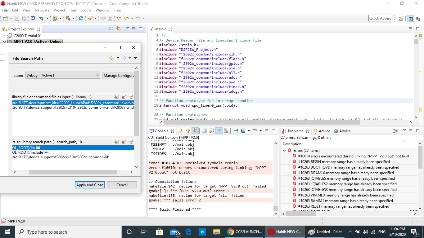
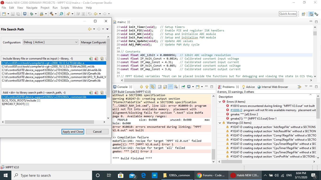
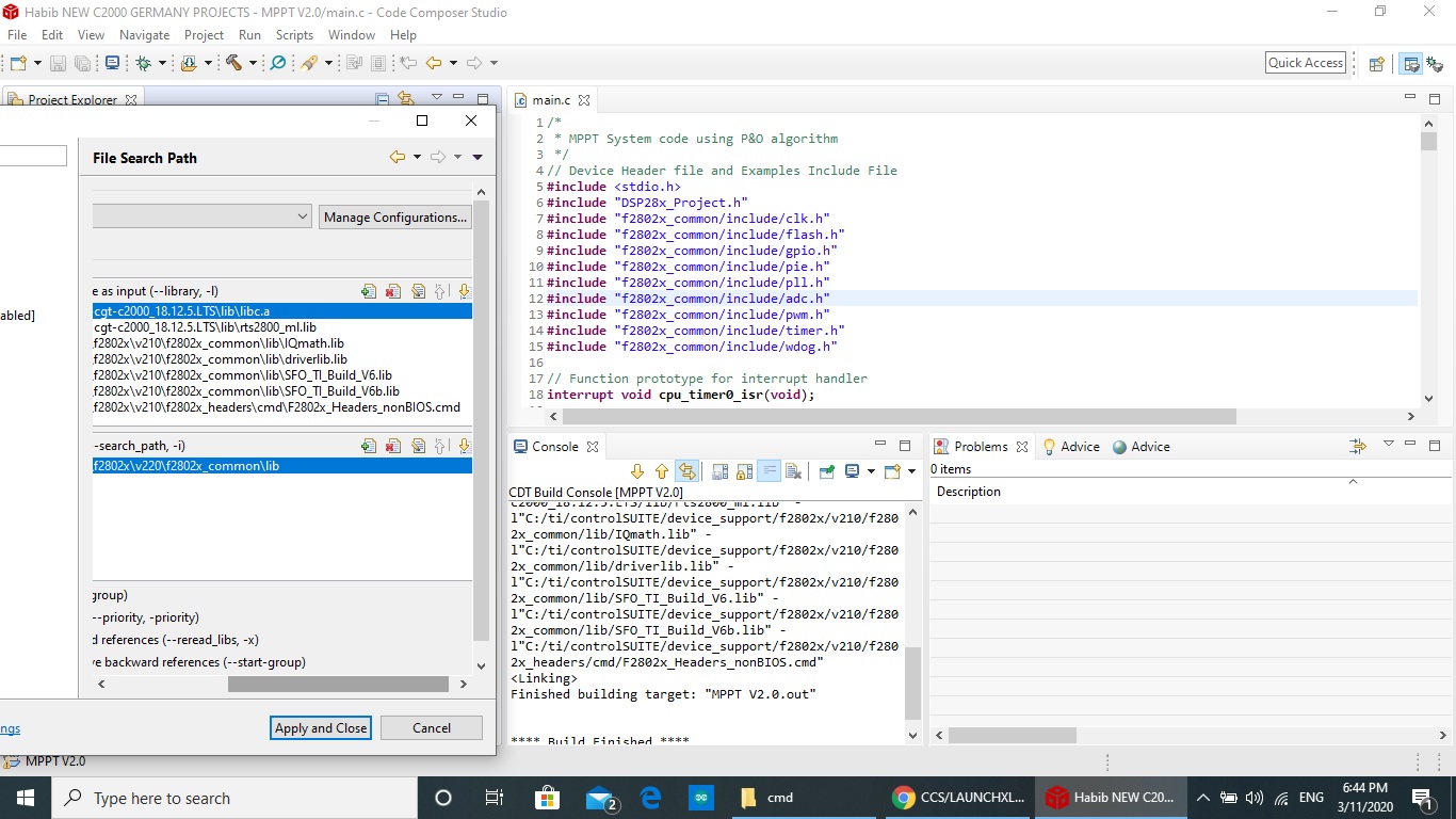
so i came across a code online and wanted to run on on my CCS, however i'm having a difficult time to get it to run due errors with include and linking paths, i would appreciate some help getting those fixed.
down below you could see the code i copied online and screen shots of the issues
/*

*/
// Device Header file and Examples Include File
#include <stdio.h>
#include "DSP28x_Project.h"
#include "f2802x_common/include/clk.h"
#include "f2802x_common/include/flash.h"
#include "f2802x_common/include/gpio.h"
#include "f2802x_common/include/pie.h"
#include "f2802x_common/include/pll.h"
#include "f2802x_common/include/adc.h"
#include "f2802x_common/include/pwm.h"
#include "f2802x_common/include/timer.h"
#include "f2802x_common/include/wdog.h"
// Function prototype for interrupt handler
interrupt void cpu_timer0_isr(void);
// Function prototypes
void init_system(void); // Initialise all handles, disable watch dog, clocks, disable the PIE and all interrupts
void init_Gpio(void); // Setup Gpio pins
void init_Timer(void); // Setup timers
void init_PIE(void); // Enable PIE and register ISR handlers
void init_ADC(void); // Setup and initialize ADC module
void Init_Pwm(void); // Setup and initialise PWM module
void Data_Update(void); // Update ADC values
void Adj_PWM(void); // Update PWM duty cycle
// Constants
const float ADC_12bit = 0.0008056; // 12bit ADC voltage resolution
const float IP_Volt_Const = 0.0814; // Calibrated constant input voltage
const float IP_Amp_Const = 4.31; // Calibrated constant input current
const float OP_Volt_Const = 0.085; // Calibrated constant output voltage
const float OP_Amp_Const = 3.6; // Calibrated constant output current
// MPPT Global variables *Most can be placed inside the functions but for debugging and viewing the state in CCS they need to be Global
float IP_Amp;
float IP_Volt;
float Old_IP_Volt;
float OP_Amp;
float OP_Volt;
float New_PW_In;
float Old_PW_In;
float New_PW_Out;
int SysTick = 0; // Used to control the PWM update frequency
int PWM_Temp_Temp; // Used for graphing data
int Duty_Cycle; // Used for graphing data
//System handles
CLK_Handle myClk;
FLASH_Handle myFlash;
GPIO_Handle myGpio;
ADC_Handle myAdc;
PIE_Handle myPie;
TIMER_Handle myTimer0, myTimer1;
CPU_Handle myCpu;
PLL_Handle myPll;
WDOG_Handle myWDog;
PWM_Handle myPwm1, myPwm2;
void main(void)
{
init_system();
init_Gpio();
init_Timer();
init_PIE();
init_ADC();
// Disables the ePWM module time base clock sync signal
CLK_disableTbClockSync(myClk);
Init_Pwm();
// Enables the ePWM module time base clock sync signal
CLK_enableTbClockSync(myClk);
Data_Update(); // initial read of current power in
while(1)
{
if (SysTick == 1)
{
Data_Update();
Adj_PWM();
SysTick = 0;
}
}
}
// Function declaration for the interrupt handler
interrupt void cpu_timer0_isr(void)
{
SysTick = 1;
PIE_clearInt(myPie, PIE_GroupNumber_1);
}
// Function declarations
void init_system(void)
{
// Initialise all the handles needed for this application
myPwm1 = PWM_init((void *)PWM_ePWM1_BASE_ADDR, sizeof(PWM_Obj));
myPwm2 = PWM_init((void *)PWM_ePWM2_BASE_ADDR, sizeof(PWM_Obj));
myAdc = ADC_init((void *)ADC_BASE_ADDR, sizeof(ADC_Obj));
myClk = CLK_init((void *)CLK_BASE_ADDR, sizeof(CLK_Obj));
myCpu = CPU_init((void *)NULL, sizeof(CPU_Obj));
myFlash = FLASH_init((void *)FLASH_BASE_ADDR, sizeof(FLASH_Obj));
myGpio = GPIO_init((void *)GPIO_BASE_ADDR, sizeof(GPIO_Obj));
myPie = PIE_init((void *)PIE_BASE_ADDR, sizeof(PIE_Obj));
myPll = PLL_init((void *)PLL_BASE_ADDR, sizeof(PLL_Obj));
myTimer0 = TIMER_init((void *)TIMER0_BASE_ADDR, sizeof(TIMER_Obj));
myTimer1 = TIMER_init((void *)TIMER1_BASE_ADDR, sizeof(TIMER_Obj));
myWDog = WDOG_init((void *)WDOG_BASE_ADDR, sizeof(WDOG_Obj));
// Disables the watchdog (WDOG) timer
WDOG_disable(myWDog);
// Enables the ADC clock
CLK_enableAdcClock(myClk);
// Calibrates the ADC and internal oscillators
(*Device_cal)();
// Sets the internal oscillator 1 as the clock source
CLK_setOscSrc(myClk, CLK_OscSrc_Internal);
// Setup the PLL for x12 /1 which will yield 60Mhz = 10Mhz * 12 / 2
PLL_setup(myPll, PLL_Multiplier_12, PLL_DivideSelect_ClkIn_by_2);
// Disables the peripheral interrupt expansion (PIE)
PIE_disable(myPie);
// Disables all of the interrupts
PIE_disableAllInts(myPie);
// Disables global interrupts
CPU_disableGlobalInts(myCpu);
// Clears all interrupt flags
CPU_clearIntFlags(myCpu);
// Enable Global realtime interrupt DBGM
CPU_enableDebugInt(myCpu);
}
void init_Gpio()
{
// Initalize GPIO for EPWM1A
GPIO_setPullUp(myGpio, GPIO_Number_0, GPIO_PullUp_Disable);
//GPIO_setPullUp(myGpio, GPIO_Number_1, GPIO_PullUp_Disable); // Note used
GPIO_setMode(myGpio, GPIO_Number_0, GPIO_0_Mode_EPWM1A);
//GPIO_setMode(myGpio, GPIO_Number_1, GPIO_1_Mode_EPWM1B); // Note used
// Initalize GPIO for EPWM2A
GPIO_setPullUp(myGpio, GPIO_Number_2, GPIO_PullUp_Disable);
//GPIO_setPullUp(myGpio, GPIO_Number_3, GPIO_PullUp_Disable); // Note used
GPIO_setMode(myGpio, GPIO_Number_2, GPIO_2_Mode_EPWM2A);
//GPIO_setMode(myGpio, GPIO_Number_3, GPIO_3_Mode_EPWM2B); // Note used
}
void init_Timer()
{
// Sets the timer (TIMER) period
TIMER_setPeriod(myTimer0, 6000000);
// Sets the timer (TIMER) prescaler
TIMER_setPreScaler(myTimer0, 0);
// Reloads the timer (TIMER) value
TIMER_reload(myTimer0);
// Sets the timer (TIMER) emulation mode
TIMER_setEmulationMode(myTimer0, TIMER_EmulationMode_RunFree);
// Enables the timer (TIMER) interrupt
TIMER_enableInt(myTimer0);
//Starts the timer (TIMER)
TIMER_start(myTimer0);
}
void init_PIE(void)
{
// Initializes the vector table with Debug interrupt handlers
PIE_setDebugIntVectorTable(myPie);
// Enables the peripheral interrupt expansion (PIE)
PIE_enable(myPie);
// Registers a handler for a PIE interrupt
PIE_registerPieIntHandler(myPie, PIE_GroupNumber_1, PIE_SubGroupNumber_7, (intVec_t)&cpu_timer0_isr);
// Enables a specified interrupt number
CPU_enableInt(myCpu, CPU_IntNumber_1);
// Enables the Cpu Timer 0 interrupt
PIE_enableTimer0Int(myPie);
// Enables global interrupts
CPU_enableGlobalInts(myCpu);
// Enables the debug interrupt
CPU_enableDebugInt(myCpu);
}
void init_ADC(void)
{
// Enables the ADC band gap circuit
ADC_enableBandGap(myAdc);
// Enables the ADC reference buffers circuit
ADC_enableRefBuffers(myAdc);
// Powers up the ADC
ADC_powerUp(myAdc);
// Enables the ADC
ADC_enable(myAdc);
// ADCCTL1 - ADC_ADCCTL1_ADCREFSEL_BITS
ADC_setVoltRefSrc(myAdc, ADC_VoltageRefSrc_Int);
// Clear ADCINT1 flag reinitialize for next SOC
ADC_clearIntFlag(myAdc, ADC_IntNumber_1);
// Enables the specified ADC interrupt
PIE_enableAdcInt(myPie, ADC_IntNumber_1);
// Enables the ADC interrupt
ADC_enableInt(myAdc, ADC_IntNumber_1);
// Sets the interrupt pulse generation mode
ADC_setIntPulseGenMode(myAdc, ADC_IntPulseGenMode_Prior);
// Enables ADC interrupt
ADC_enableInt(myAdc, ADC_IntNumber_1);
// Sets the interrupt mode
ADC_setIntMode(myAdc, ADC_IntNumber_1, ADC_IntMode_ClearFlag);
// Sets the interrupt source
ADC_setIntSrc(myAdc, ADC_IntNumber_1, ADC_IntSrc_EOC7);
// Sets the start-of-conversion (SOC) channel number
ADC_setSocChanNumber (myAdc, ADC_SocNumber_0, ADC_SocChanNumber_A0);
ADC_setSocChanNumber (myAdc, ADC_SocNumber_1, ADC_SocChanNumber_A1);
ADC_setSocChanNumber (myAdc, ADC_SocNumber_2, ADC_SocChanNumber_A2);
ADC_setSocChanNumber (myAdc, ADC_SocNumber_3, ADC_SocChanNumber_A3);
ADC_setSocChanNumber (myAdc, ADC_SocNumber_4, ADC_SocChanNumber_A0);
ADC_setSocChanNumber (myAdc, ADC_SocNumber_5, ADC_SocChanNumber_A1);
ADC_setSocChanNumber (myAdc, ADC_SocNumber_6, ADC_SocChanNumber_A2);
ADC_setSocChanNumber (myAdc, ADC_SocNumber_7, ADC_SocChanNumber_A3);
// Sets the start-of-conversion (SOC) trigger source
ADC_setSocTrigSrc(myAdc, ADC_SocNumber_0, ADC_SocTrigSrc_EPWM1_ADCSOCA);
ADC_setSocTrigSrc(myAdc, ADC_SocNumber_1, ADC_SocTrigSrc_EPWM1_ADCSOCA);
ADC_setSocTrigSrc(myAdc, ADC_SocNumber_2, ADC_SocTrigSrc_EPWM1_ADCSOCA);
ADC_setSocTrigSrc(myAdc, ADC_SocNumber_3, ADC_SocTrigSrc_EPWM1_ADCSOCA);
ADC_setSocTrigSrc(myAdc, ADC_SocNumber_4, ADC_SocTrigSrc_EPWM1_ADCSOCA);
ADC_setSocTrigSrc(myAdc, ADC_SocNumber_5, ADC_SocTrigSrc_EPWM1_ADCSOCA);
ADC_setSocTrigSrc(myAdc, ADC_SocNumber_6, ADC_SocTrigSrc_EPWM1_ADCSOCA);
ADC_setSocTrigSrc(myAdc, ADC_SocNumber_7, ADC_SocTrigSrc_EPWM1_ADCSOCA);
// Sets the start-of-conversion (SOC) sample delay
ADC_setSocSampleWindow(myAdc, ADC_SocNumber_0, ADC_SocSampleWindow_55_cycles);
ADC_setSocSampleWindow(myAdc, ADC_SocNumber_1, ADC_SocSampleWindow_55_cycles);
ADC_setSocSampleWindow(myAdc, ADC_SocNumber_2, ADC_SocSampleWindow_55_cycles);
ADC_setSocSampleWindow(myAdc, ADC_SocNumber_3, ADC_SocSampleWindow_55_cycles);
ADC_setSocSampleWindow(myAdc, ADC_SocNumber_4, ADC_SocSampleWindow_55_cycles);
ADC_setSocSampleWindow(myAdc, ADC_SocNumber_5, ADC_SocSampleWindow_55_cycles);
ADC_setSocSampleWindow(myAdc, ADC_SocNumber_6, ADC_SocSampleWindow_55_cycles);
ADC_setSocSampleWindow(myAdc, ADC_SocNumber_7, ADC_SocSampleWindow_55_cycles);
}
void Init_Pwm()
{
// Enables the pwm clock
CLK_enablePwmClock(myClk, PWM_Number_1);
// Enables the pulse width modulation (PWM) start of conversion (SOC) A pulse generation
PWM_enableSocAPulse(myPwm1);
// Enables the pulse width modulation (PWM) start of conversion (SOC) A pulse generation
PWM_setSocAPulseSrc(myPwm1, PWM_SocPulseSrc_CounterEqualCmpAIncr);
// Sets the pulse width modulation (PWM) start of conversion (SOC) A interrupt period
PWM_setSocAPeriod(myPwm1, PWM_SocPeriod_FirstEvent);
// TBCTL Time-Base Control Register - syncmode PWM_TBCTL_SYNCOSEL_BITS
PWM_setSyncMode(myPwm1, PWM_SyncMode_CounterEqualZero);
// TBPRD Time Base Period Register
PWM_setPeriod(myPwm1, 1000); // 60M /
// Sets the pulse width modulation (PWM) phase
PWM_setPhase(myPwm1, 0x0000);
// Sets the pulse width modulation (PWM) count
PWM_setCount(myPwm1, 0x0000);
// Sets the pulse width modulation (PWM) counter mode
PWM_setCounterMode(myPwm1, PWM_CounterMode_UpDown);
// Disables the pulse width modulation (PWM) counter loading from the phase register
PWM_disableCounterLoad(myPwm1);
// Sets the pulse width modulation (PWM) high speed clock divisor
PWM_setHighSpeedClkDiv(myPwm1, PWM_HspClkDiv_by_2);
// Sets the pulse width modulation (PWM) clock divisor
PWM_setClkDiv(myPwm1, PWM_ClkDiv_by_1);
// Writes the pulse width modulation (PWM) data value to the Counter Compare A hardware
PWM_setCmpA(myPwm1, 500);
// Sets the pulse width modulation (PWM) object action for PWM A when the counter equals CMPA and the counter is incrementing
PWM_setActionQual_CntUp_CmpA_PwmA(myPwm1, PWM_ActionQual_Set);
// Sets the pulse width modulation (PWM) object action for PWM A when the counter equals CMPA and the counter is decrementing
PWM_setActionQual_CntDown_CmpA_PwmA(myPwm1, PWM_ActionQual_Clear);
// Sets the pulse width modulation (PWM) object action for PWM B when the counter equals CMPA and the counter is incrementing
PWM_setActionQual_CntUp_CmpA_PwmB(myPwm1, PWM_ActionQual_Clear);
// Sets the pulse width modulation (PWM) object action for PWM B when the counter equals CMPA and the counter is decrementing
PWM_setActionQual_CntDown_CmpA_PwmB(myPwm1, PWM_ActionQual_Set);
// Enables the pwm clock
CLK_enablePwmClock(myClk, PWM_Number_2);
// Sets the pulse width modulation (PWM) sync mode
PWM_setSyncMode(myPwm2, PWM_SyncMode_EPWMxSYNC);
// Sets the pulse width modulation (PWM) period
PWM_setPeriod(myPwm2, 1000);
// Enables the pulse width modulation (PWM) counter loading from the phase register
PWM_enableCounterLoad(myPwm2);
// Sets the pulse width modulation (PWM) phase
PWM_setPhase(myPwm2, 1000); // To calc phase 2000 = 180deg therefore 2000 /180 = 11.11 so for 120deg = 120*11.11 = 1333.2
// Sets the pulse width modulation (PWM) phase direction
PWM_setPhaseDir(myPwm2, PWM_PhaseDir_CountUp);
// Sets the pulse width modulation (PWM) counter mode
PWM_setCounterMode(myPwm2, PWM_CounterMode_UpDown);
// Sets the pulse width modulation (PWM) high speed clock divisor
PWM_setHighSpeedClkDiv(myPwm2, PWM_HspClkDiv_by_2);
// Sets the pulse width modulation (PWM) clock divisor
PWM_setClkDiv(myPwm2, PWM_ClkDiv_by_1);
// Writes the pulse width modulation (PWM) data value to the Counter Compare A hardware
PWM_setCmpA(myPwm2, 500);
// Sets the pulse width modulation (PWM) object action for PWM A when the counter equals CMPA and the counter is incrementing
PWM_setActionQual_CntUp_CmpA_PwmA(myPwm2, PWM_ActionQual_Set);
// Sets the pulse width modulation (PWM) object action for PWM A when the counter equals CMPA and the counter is decrementing
PWM_setActionQual_CntDown_CmpA_PwmA(myPwm2, PWM_ActionQual_Clear);
// Sets the pulse width modulation (PWM) object action for PWM B when the counter equals CMPA and the counter is incrementing
PWM_setActionQual_CntUp_CmpA_PwmB(myPwm2, PWM_ActionQual_Clear);
// Sets the pulse width modulation (PWM) object action for PWM B when the counter equals CMPA and the counter is decrementing
PWM_setActionQual_CntDown_CmpA_PwmB(myPwm2, PWM_ActionQual_Set);
}
void Data_Update(void)
{
float ADC_A0, ADC_A1, ADC_A2, ADC_A3;
int sum_of_ADC_samples_Array[4] = { 0 };
int numberOfSamples = 64;
int i = 0;
for (i = 0; i < numberOfSamples; i++) {
while (AdcRegs.ADCINTFLG.bit.ADCINT1 == 0) {}
sum_of_ADC_samples_Array[0] += AdcResult.ADCRESULT0;
sum_of_ADC_samples_Array[1] += AdcResult.ADCRESULT1;
sum_of_ADC_samples_Array[2] += AdcResult.ADCRESULT2;
sum_of_ADC_samples_Array[3] += AdcResult.ADCRESULT3;
sum_of_ADC_samples_Array[0] += AdcResult.ADCRESULT4;
sum_of_ADC_samples_Array[1] += AdcResult.ADCRESULT5;
sum_of_ADC_samples_Array[2] += AdcResult.ADCRESULT6;
sum_of_ADC_samples_Array[3] += AdcResult.ADCRESULT7;
AdcRegs.ADCINTFLGCLR.bit.ADCINT1 = 1;
}
// divide by the number of samples to find the average value
ADC_A0 = sum_of_ADC_samples_Array[0] / 128;
ADC_A1 = sum_of_ADC_samples_Array[1] / 128;
ADC_A2 = sum_of_ADC_samples_Array[2] / 128;
ADC_A3 = sum_of_ADC_samples_Array[3] / 128;
// Calculate values read on ADC GPIO
ADC_A0 = (ADC_12bit * ADC_A0);
ADC_A1 = (ADC_12bit * ADC_A1);
ADC_A2 = (ADC_12bit * ADC_A2);
ADC_A3 = (ADC_12bit * ADC_A3);
// Calculate correct circuit readings
IP_Volt = (ADC_A0 / IP_Volt_Const);
IP_Amp = (ADC_A1 / IP_Amp_Const);
OP_Volt = (ADC_A2 / OP_Volt_Const);
OP_Amp = (ADC_A3 / OP_Amp_Const);
// Calculate Power In and Power Out
New_PW_In = IP_Volt * IP_Amp;
New_PW_Out = OP_Volt * OP_Amp;
}
void Adj_PWM(void)
{
int PWM_Temp;
PWM_Temp = EPwm1Regs.CMPA.half.CMPA; // Assign the current duty cycle value of PWM1 CMPA to PWM_Temp
PWM_Temp_Temp = PWM_Temp; // Used for graphing
Duty_Cycle = 100 - ((PWM_Temp_Temp / 1000) * 100); // Used for graphing
if (New_PW_In > Old_PW_In) { // New power larger than old power
if (IP_Volt > Old_IP_Volt) // New PV volts greater than old
{
PWM_Temp + 2; // Increase Duty Cycle
}
else // New PV volts less than old
{
PWM_Temp - 2; // Decrease Duty Cycle
}
}
else { // New power less than old power
if (IP_Volt > Old_IP_Volt) // New PV volts greater than old
{
PWM_Temp - 2; // Decrease Duty Cycle
}
else // New PV volts less than old
{
PWM_Temp + 2; // Increase Duty Cycle
}
}
if (PWM_Temp < 100) {
PWM_Temp = 100; // Necessary to prevent too smaller PWM value
}
if (PWM_Temp > 900) {
PWM_Temp = 900; // Necessary to prevent too greater PWM value
}
EPwm1Regs.CMPA.half.CMPA = PWM_Temp; // Adjust PWM1 duty cycle
EPwm2Regs.CMPA.half.CMPA = PWM_Temp; // Adjust PWM2 duty cycle
Old_IP_Volt = IP_Volt; // Assign new input volts value to old input volts value
Old_PW_In = New_PW_In; // Assign new power value to old power value
}
error is
**** Build of configuration Debug for project MPPT V2.0 ****
"C:\\ti\\ccs930\\ccs\\utils\\bin\\gmake" -k -j 8 all -O
Building file: "../main.c"
Invoking: C2000 Compiler
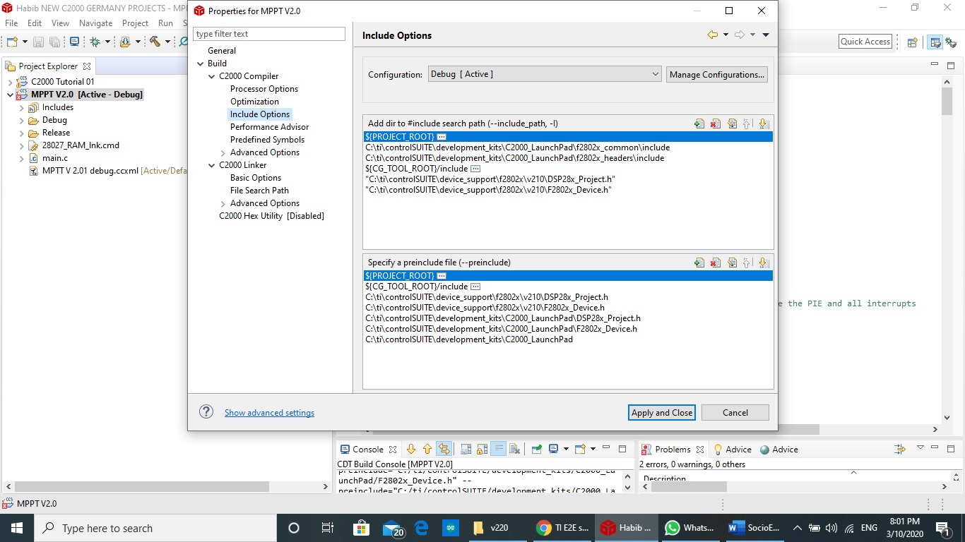
"C:/ti/ccs930/ccs/tools/compiler/ti-cgt-c2000_18.12.5.LTS/bin/cl2000" -v28 -ml -mt --include_path="C:/ti/Habib NEW C2000 GERMANY PROJECTS/MPPT V2.0" --include_path="C:/ti/controlSUITE/development_kits/C2000_LaunchPad/f2802x_common/include" --include_path="C:/ti/controlSUITE/development_kits/C2000_LaunchPad/f2802x_headers/include" --include_path="C:/ti/ccs930/ccs/tools/compiler/ti-cgt-c2000_18.12.5.LTS/include" --include_path="C:/ti/controlSUITE/device_support/f2802x/v210/DSP28x_Project.h" --include_path="C:/ti/controlSUITE/device_support/f2802x/v210/F2802x_Device.h" --preinclude="C:/ti/Habib NEW C2000 GERMANY PROJECTS/MPPT V2.0" --preinclude="C:/ti/ccs930/ccs/tools/compiler/ti-cgt-c2000_18.12.5.LTS/include" --preinclude="C:/ti/controlSUITE/device_support/f2802x/v210/DSP28x_Project.h" --preinclude="C:/ti/controlSUITE/device_support/f2802x/v210/F2802x_Device.h" --preinclude="C:/ti/controlSUITE/development_kits/C2000_LaunchPad/DSP28x_Project.h" --preinclude="C:/ti/controlSUITE/development_kits/C2000_LaunchPad/F2802x_Device.h" --preinclude="C:/ti/controlSUITE/development_kits/C2000_LaunchPad" --advice:performance=all -g --diag_warning=225 --diag_wrap=off --display_error_number --abi=coffabi --preproc_with_compile --preproc_dependency="main.d_raw" "../main.c"
>> Compilation failure
subdir_rules.mk:9: recipe for target 'main.obj' failed
Command-line error #1966: cannot open source file "C:/ti/Habib NEW C2000 GERMANY PROJECTS/MPPT V2.0": Invalid argument
1 catastrophic error detected in the compilation of "../main.c".
Compilation terminated.
gmake: *** [main.obj] Error 1
gmake: Target 'all' not remade because of errors.
**** Build Finished ****