This thread has been locked.

If you have a related question, please click the "Ask a related question" button in the top right corner. The newly created question will be automatically linked to this question.

CCS/ENERGYTRACE: Way-off current measurement on a RF system

Part Number: ENERGYTRACE
Other Parts Discussed in Thread: MSP-FET, , CC1101

Tool/software: Code Composer Studio

Hi,

I'm working with a MSP430 and a RF module. Usual RF stuff involves sleeping most of the time, sending a burst of data, and going back to sleep. My application loop is :

- sleeping (approx. 1s)

- TX (around 0.9ms)

- RX (around 10ms)

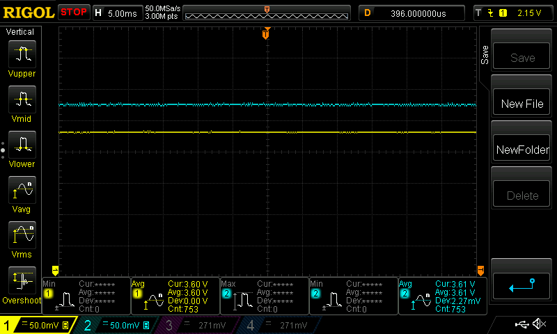
I'm powering the system with the MSP-FET as usual (I've been using it for 3 years and don't have issues with it on other non-RF projects).

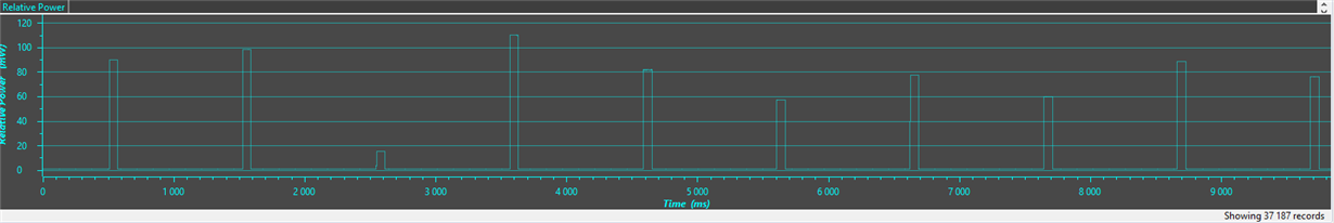
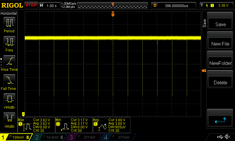
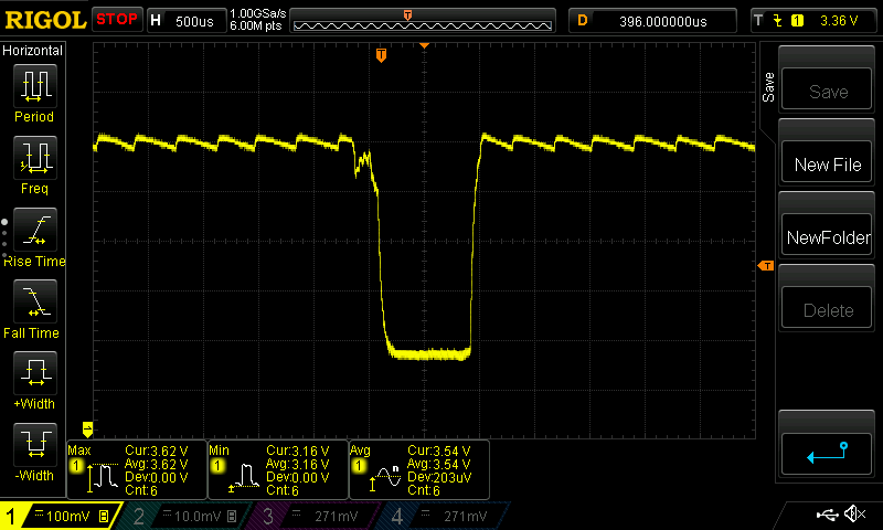
Reference measurements are taken with a scope and a 10-ohm resistor on the low-side (GND). I got these results :

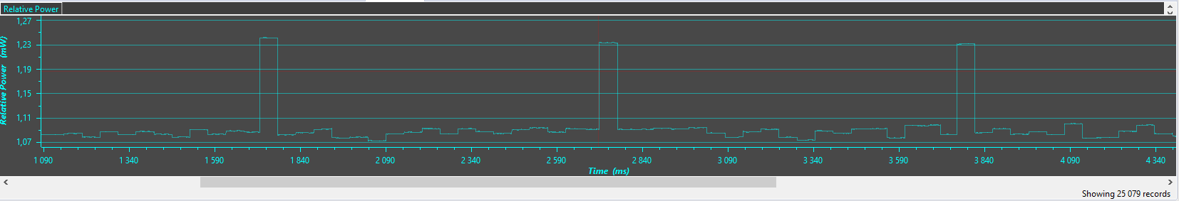
Below is a current measurement of the system on multi-seconds scale.

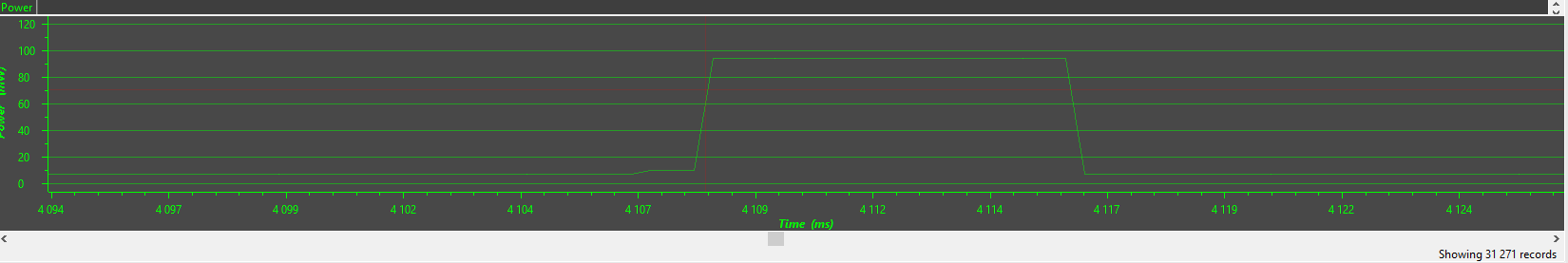
Below isa current measurement of the system of a single burst zoomed

All looks correct regarding the system specs and what it acutally does.

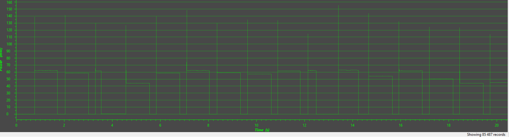
On the other hand, when removing the scope and resistor and measuring the current with EnergyTrace, I got the following results.

Below is the current measurement of the system on a multi-second scale

Below is a zoom on a single burst

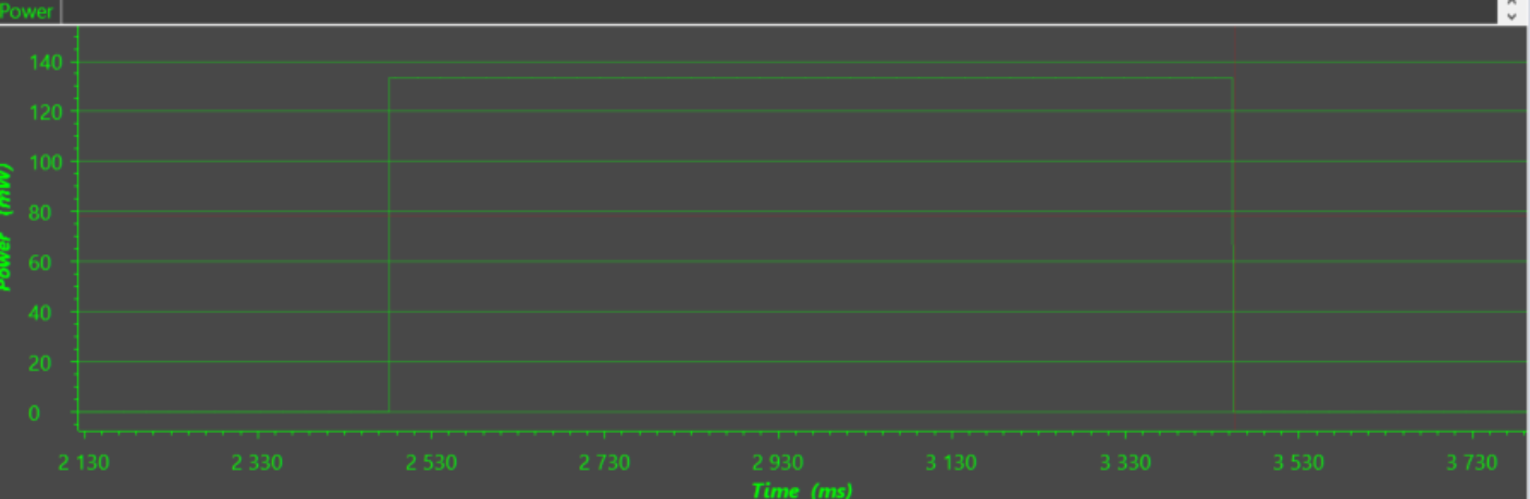
EnergyTrace actually thinks that the current bursts lasts around 1s !

And the average current given by EnergyTrace is around 8mA where the correct measurement is around 170µA

The EnergyTrace weird measrements are reproduced anytime but the "odd-40-60mW current staying after the burst" duration looks random

I'm not sure where the problem stands inside EnergyTrace.

Additional infos :

- I'm using CodeComposerStudio v9.3.0

- In the beginning, I thought it was a bug with the RF module and posted a ticket ( http://e2e.ti.com/support/wireless-connectivity/sub-1-ghz/f/156/t/865643 ) before I actually measured current with a scope and a resistor

  • Hi Romain,

    Could you show your hardware connected when use  EnergyTrace to measure current consumption?

    In order to ensure the accuracy of the measurement when using the EnergyTrace tool, only the power pins (VCC and GND) should be connected between the MSP-FET and board.

    Best Regards

    Johnson

  • Hi Johnson,

    That's what I'm doing.

    The wiring is the following (don't have picture right here as I don't have the board with me right now) :

    - The MCU is linked to the RF chip with the usual SPI bus.

    - They are both powered directly through VCC and GND from the FET (VCC_TOOL) and that's it.

    When I tried to test the same circuit on a launchpad (FR5969, FR24433) equipped with EnergyTrace, I remove all jumpers and only take 3V3/GND out to my system.

    I also thought it may come from the RF chip itself so I tried with another brand/model doing the same loop and still comes to the same results.

  • Hi Romain,

    Do you work in debug mode or free run mode when testing these currents? The power consumption measured in debug mode may be different from the actual one. In order to get the power consumption accurately, you need to run in free run mode.

    Best Regards

    Johnson

  • Hi Johnson,

    I'm always working either :

    -on free run

    - just with VCC/GND wires (no test/reset/rx/tx, so no debug)

    As I said I've been using the EnergyTrace on a lot of other projets throught the years and never had this issue.

  • Hi Romain,

    I am not sure if the RF module has affected this EnergyTrace measurement, so can you remove the RF module and use the Oscilloscope and EnergyTrace alone to measure the power consumption of the MSP430 and compare their results?

    Best Regards

    Johnson

  • Hi Johnson,

    I've rebuilt a easier setup for that (complete code was waiting for the radio answer packet and stuff).

    Loop is :

    - Radio TX (continious wave) for 1ms

    - Sleep for 1000ms

    I've made 3 measurements :

    - system with Radio

    - system without Radio (replaced by a LED)

    - system with without radio nor LED

    Below are the screens of EnergyTrace :

    #1 : System with radio

    #2 : System with LED

    #3 : System with nothing

    To analyse these screens:

    #3 shows the LPM0 current => good

    #2 shows spikes of the LED => already off as the spike lasts for ~50ms in the trace. I validated the voltage of the LED with the scope and it only lasts 1ms

    #1 shows spike of TX continious waves => also way off. Interestingly, the values of the peak are not even the same and looks random

  • Hi Romain,

    Is there data captured by an oscilloscope here? It can be compared to found the root cause of the problem.


    By the way, is it convenient to attach your test program so that I can verify in my side.

    Best Regards

    Johnson

  • Hi Johnson,

    You're right, I forgot about the scope measurement. I just took them.

    To measure current with the scope, I added a 10-ohm resistor on the high-side (between the 3.6V regulated voltage and the system VCC. I then measured the voltage and looks for the "drops" in VCC.

    Below are screens of the scope for with and without RF module

    Drops of TX continious wave every second. Drops value is repeatable and stable

    Zoom on a single drop. It lasts for about 1ms. Drop value is 460mV => 46mA (close to expected)

    No Radio. Voltage is very stable but interesting value (LPM0 current) is under the radar here.

    RF module for test is CC1101. Simple setup code is attachedCC1101_Test.zip

    Best regards,

    Romain

  • Hi Romain,

    Let's analyze these two waveforms:

    under the same test environment, TX-> 1ms, Sleep-> 1S.

    Result : It seems that the result measured by EnergyTrace matches the data measured by the oscilloscope, and there a other problem is that the values of the peak are not even the same and looks random.

    And it does not appear that the current burst lasted around 1S you provided at the earliest. 

    Is there any difference in the measurement environment of the following two EneryTrace measurement results?

    Best Regards

    Johnson

  • Hi Johnson,

    Thanks for your reply.

    On your first analysis, I'd like to differ.

    The results of EnergyTrace does not match the scope. Energytrace shows peaks that lasts for 50ms where the scope peaks only last for the correct 1ms.

    As for the difference between the the earliest results, the earliest results were of the complete system with TX,RX and packet stuff.

    I've found that depending on what state the RF chip end in (Power-down or Idle for example) between each TX wave, the EnergyTrace peaks has not the same duration at all.

    To illustrate this :

    - with the code I provided, the RF finishes in PowerDown mode and the EnergyTrace peaks lasts for ~50ms instead of 1ms

    - if I comment the "SpiStrobe(CC1101_SPWD);" : the RF chip does not go into PowerDown mode and only stays in Idle), the TX peaks seen by the EnergyTrace lasts for 8ms (still off). See the screenshot below.

    On the other side, the scope always see the same peak duration : 1ms (which is the correct one). The only difference seen on scope is the base current value (Idle instead of PowerDown).

    The more I dig into this, the less I understand. Why changing base current draw of the system would make the EnergyTrace peaks measures more or less precise ? Does EnergyTrace has multiple internal ranges it switches between (like millis and micro) and loose precision if switches are too fast ?

  • Hi Romain,

    Energytrace use a digital Non-synchronous Buck running in discontinues mode to measure the power consumption.

    Therefore, the main measurement object is power consumption, and the current information is obtained through calculation, so there may be some bias.

    Best Regards

    Johnson

  • Hi Johnson,

    Thank you for this information.

    So if I understand, the buck is charging a buffer (probably a capacitor) in an asynchronous way and monitor the charge and discharge of this buffer by the load to adjust next duty-cycle ?

    So our culprit here would be that when the high-current happens, it starts running higher duty-cycle. Then, the low-current returns and it takes some time for the buffer to actually discharge so the buck may see the difference.

    I've made some experiments on that way by looking at the post-TX current error duration and comparing it with the idle power. I've removed all the LPM0 stuff and doing active wait to avoid delays and measure more accuratly.

    - When putting RF back to sleep (base power = 1.12mW), the error is always ~50ms (not depending on the TX duration itself)

    - When putting RF back to idle (base power = 7.61mW), the error is always ~8ms

    The values confirms the suspicion (6.8 time more base current leads to a 6.3 less error).

    That leads us to compute the actual error buffer size to be around 7.61*8 = 60.8 mW.ms = 60.8µW.s = 60.8µJ

    That means that right now, the EnergyTrace is precise when doing low-power only and high-power only, but has a huge issue when swinging from high to low power (typically RF stuff, including most of IoT application with very short bursts)

    Johnson, do you think that this "buffer" causing issue would be physically in the form of a capacitor (probably buck output capacitor) and where it would be located to experiment with it. I think that changing it to a lower value may causes a bit more of drop with going from low-to-high power but may reduces the high-to-low error.

    Best regards,

    Romain

  • I've looked into the EnergyTrace schematic (for example p.41 of slau535b) and the 13/329073 patent.

    So EnergyTrace is (quite smart by the way) sending finite-energy pulse to the buck. My guess about actually measuring is counting the number of pulses sent over a period.

    So I've tapped and looked on the scope what actually happenned on the Buck side (EZFET_DCDCPULSE and EZFET_VCCOUT) on the scope to see if something weird happens here that could actually explains the issue.

    Below are scope catpures

    Single TX burst (CH1 : EZFET_DCDCPULSE, CH2 : EZFET_VCCOUT).

    Here we see clearly the increase in drops and regulation pulses (so increased power consumption)

    Zoomed-out TX burst with 100ms after. Surprisingly, I don't see anything on EZFET_DCDCPULSE frequency changing during the next 100ms. However, EnergyTrace software see a constant high-power level that lasts 50ms.

    My conclusion is that the issue must be software related (either in the MSP430G2452RSA chip used to control the Energy-Trace buck or in CodeComposerStudio itself)

  • Hi Romain,

    It seems that your suspicion is reasonable. I will summarize it and discuss with relevant departments, and then come back to discuss further.

    Best Regards

    Johnson

  • Hi Romain,

    After the discussion, we also agree with your conclusion. As you analyzed the EnergyTrace schematic and measurement principle, this situation should be related to the firmware in the EnergyTrace hardware and the enerytrace tool in CCS. Thank you for your analysis and feedback. We will optimize in later versions.


    Thanks again!

    Best Regards

    Johnson

  • Hi Johnson,

    Thank you for working on it and identify it as a bug.

    Concerning a fix :

    - Were you able to reproduce the issue on your side (or want help with exact CCS version/debug probe that I use) ?

    - When you mean "later versions", do you have an ETA for this fix ? Will this be as a hotfix or will it be embedded in a later general update ?

    With the bug right now, the use of Energytrace is completely broken an useless for that type of application (IoT with quick TX/RX turnover), so it would be nice to have a fix soon.

    Best regards,

    Romain

  • Hi Romain,

    We have not reproduced this problem here, but it is in progress, which is also the work that must be done to analyze and update the new version of the firmware.(I see you have provided your CCS version and related content.)
    For these abnormal functions, we will update and maintain new versions as needed, including the firmware on the hardware board and Enerytrace tools in CCS.

    Thanks again!

    Best Regards

    Johnson