This thread has been locked.
If you have a related question, please click the "Ask a related question" button in the top right corner. The newly created question will be automatically linked to this question.
Tool/software: Code Composer Studio
In tiware directory there is sample of program called blinky. I build this program using composer studio but how I can build binary which can be programed in on chip flash which I can run after reset or power cycle.
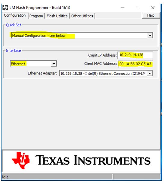
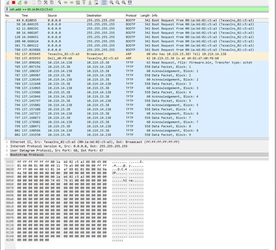
I tool blinky.bin file and with lm flash programmer programmed blinky.bin starting at address 0x4000 , but I cannot see it running and blinding LED.
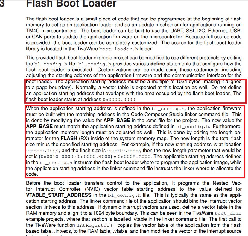
What are the steps to build so it will run programmed at address 0x4000.
Thaks
Hi,
You cannot just start your application at 0x4000 unless you have a bootloader starting at 0x0. The processor after reset expects a valid stack pointer and reset vector at 0x0 and 0x4. If you don't have a bootloader than it means there is nothing between 0x0 and 0x4000. You binary will not work. You either need to have your application starts at 0x0 or you have a bootloader starts at 0x0 that will jump to your application at 0x4000.
Hi Charles ,
Thanks for prompt reply.
So if I put my boot loader sample of which is in tiware\bootloader
and modify it that it will load blincky application which I build from TIWARE subdirectory.,
Where your bootloader pace this blink application ?
Will it put it starting 0x4000 ?
Will bootloader will load this app on reboot ?
Do I need to modify it further ?
Will bootloder overwrite itself by placing app in its own location?
In my case when I asked bootloader to put blinky.bin and reboot I do not see any blinking.
What step I need to do to put bootlooader permanently v at location 0 and after I erase my app at 0x4000, will it replace app , and start from location 0x4000
of it is not erased ?
Thanks
Thanks
Hi,
I will suggest you try the serial bootloader example and have a feel how it works. You can find the serial bootloader in <TivaWare_Installation>/examples/boards/ek-tm4c1294xl/boot_serial. The bootloader will program the application firmware (boot_demo1) at address starting 0x4000. The boot_demo1 application is a simple blinky program but with additional capability to listen for command to jump back to the bootloader.
In the bootlaoder project you will find the file bl_config.h and you can specify where the application address will be. See below.
//*****************************************************************************
//
// The starting address of the application. This must be a multiple of 1024
// bytes (making it aligned to a page boundary). A vector table is expected at
// this location, and the perceived validity of the vector table (stack located
// in SRAM, reset vector located in flash) is used as an indication of the
// validity of the application image.
//
// The flash image of the boot loader must not be larger than this value.
//
// Depends on: None
// Exclusive of: None
// Requires: None
//
//*****************************************************************************
#define APP_START_ADDRESS 0x4000
Hi Charles:
I have this setup in my version of bl_config.h.
Let me try it and I will get back to you.
Thanks
Hi Charles
Here is what i
did .
I programmed enet boot-loader into flash at location 0x0
]program blinky.bin and flash location 0x4000
with lm flash programmer.
Upload boot-loader and compare with source same with blinky, power cycle no blinking LED.
What is going on ? Why boot-loader cannot load blinky and run it ?
What I
am doing wrong ?
By the way if I program this sample program at location 0x0 LED start blinking.
Do I missed something here ?
Please let me know what I need to do to be able load and run this example program blinky by boot-loader.
Hi,
I asked you to try the boot_demo1.bin when using the boot_serial bootloader. Did you try?
If you are using going to implement ethernet bootloader then the bootloader to use is the boot_emac_flash and the application is the boot_demo_emac_flash.bin.
Hi Charles:
I did tried boot_demo.bin , I was trying to debug it but it hangs on
//
// Set the system clock to run at 50MHz from the PLL
//
ROM_SysCtlClockSet(SYSCTL_SYSDIV_4 | SYSCTL_USE_PLL | SYSCTL_XTAL_16MHZ |
SYSCTL_OSC_MAIN);
and it is not eve jumps to boot-loader
I am not trying to annoy you but I am trying to solve my problem building emac boot-loader.
can leave with fixed file name to tftp and fixed source and destination ip.
It look like I was able to make these changes and run it from debugger but not from stand alone bootloader which programmed in lash at address 0x4000 ans location 0x0 erased.
By the way is there way for me to debug application which is already in flash and just load symbols ?
Thanks
.
Hi,
Just one basic question. Did you run the boot_emac_flash (bootloader) to load the application (boot_demo_emac_flash.bin) examples? When I first said to use the boot_demo1.bin that was for the serial bootloader for UART. Since you wanted to use ethernet booloader, I then asked you to try the boot_emac_flash and boot_demo_emac_flash.bin instead. You do not need to modify these two examples at all. They should work out of the box.
Hi Charles , not quite ready yet
I an trying to build boot_demo_emac_flash.bin but I have in opt.h file missing includes
#include "enet_io\lwipopts.h"
#include "lwip/debug.h
Which one I should use to build ?
Hi,
Wait a minute. Did you ever touch the opt.h file in the past? There is no need to modify any of the lwIP files? Below is what I see in the opt.h file. I will suggest you download the TivaWare again and try the examples AS IS. No need to modify anything as I have already said. The examples will work out of the box.
#ifndef __LWIP_OPT_H__
#define __LWIP_OPT_H__
/*
* Include user defined options first. Anything not defined in these files
* will be set to standard values. Override anything you dont like!
*/
#include "lwipopts.h"
#include "lwip/debug.h"
Hi Charlse:
I did followed your advice get fresh copy of TivaWare_C_Series-2.1.4.178 and import
boot_demo_emac_flash project and boot_emac_flash
build them and start debugging boot_demo_emac_flash and I cannot run it past Pioutset routine.
Please tell me where I can get working example of bootloader for EK-TM4c1294XL, thta is evl board which I am using , project which I can debug or at least setpup
filename to be tftp'd from fixed ip tftfp server to EKTM4c1294XL board with fixed IP .
Can you point me to these working examples for this eval board.
HI,
How were you able to run the boot_demo_emac_flash? The boot_demo_emac_flash is an application (starting at 0x4000) which is supposed to be loaded by the bootloader (boot_emac_flash) located at 0x0. If you are said you are debugging the boot_demo_emac_flash and cannot run it past some routine then it means you probably loaded the boot_demo_emac_flash through the JTAG using CCS. Is that what you are doing? If this is not what you did, then tell me how did you load the boot_demo_emac_flash to the flash memory? If you load the boot_demo_emac_flash to the flash via JTAG in CCS, you most likely erase your bootloader at 0x0.
HI, Charles:
Here is what I am initially comes from.
I build emsc_bootloader and modify it to use fixed ip for the tftp server and eval boad as wel as file to be downloaded.
I run this from code composer studio.
My ccs yes erase all of flash.
But after running I suspect bootloader put app ( blinky from examples) on correct place.
But I do not see any blinking after power cycle.
I also run several experiments and that is why I asked initially about cook book how build, debug boot-loader. Mainly how to debug or have some kind of logging.
1 I put boot-loadre at location 0x0 , blinky 0x4000. I did nt see any blinking after power cycle.
I put blinky.bin at 0x0 and boot loader at 0x4000. LED was blinking.
Than I Erase flash from 0x0 to 0x3fff , to wipe out app and trigger boot-loader to tftp another copy but it behave totally different then debugged version.
Thanks is why I am asking all of this questions.
How I can debug boot-loader in which I pre programmed using lm flash utilities.
My use case is program boot-loader at 0x4000 load symbols into debugger and setup break point and examine variables.
There is limitation of lm programmer it cannot erase memory area where program to debug.
1. How I can program boot-loader at 0x4000 and put break points in there. Hardware break point cannot be used because I got message that address is out of range.
Can you help me just with it.
By the way separate build for boot_demo_emac_flash I cannot run with debugger.
Thanks
Sergey uskach said:1 I put boot-loadre at location 0x0 , blinky 0x4000. I did nt see any blinking after power cycle.
I put blinky.bin at 0x0 and boot loader at 0x4000. LED was blinking.
You keep using blink.bin and I have told you multiple times to use boot_demo_emac_flash. When you said blinky.bin do you really mean the simple blinky program in TivaWare or the boot_demo_emac_flash?
If the download is successful you should be able to see the application image at 0x4000 using the CCS memory browser. Once the application is loaded, if you want to debug, you simply load the symbol instead of loading the program. In CCS, you go to Run->Load->Load symbols and provide the boot_demo_emac_flash.out as your symbol. If you use LM flash programmer (acting as the tftp server and bootp server) to download the code it will also tell you if the download was successful. Tell me if you use the LM flash programmer at all?
Sergey uskach said:My use case is program boot-loader at 0x4000 load symbols into debugger and setup break point and examine variables.
The bootloader must start at 0x0 and your application will start at 0x4000? Why are you doing this differently? After reset, the CPU starts at 0x0. The bootloader will first check if there is application image present at 0x4000. If there is a stack pointer and reset vector present at 0x4000 and 0x4004 then it just jumps to the application. If the application is not present, it will boot load from the Ethernet interface. You can use the LM flash programmer to download your code. The bootloader cannot start at 0x4000 and the application at 0x0. You got it all wrong if that is what you try to do. What happens if there is no application yet and how will the processor start at 0x4000? What happens if your application is large like 512kB and how can you have the application start at 0x0 and the bootloader at 0x4000?
I really suggest you read the bootloader user's guide to be familiar with what bootlaoder is and how it works. Here is the link.
http://www.ti.com/lit/ug/spmu301e/spmu301e.pdf?&ts=1589921973858
Hi Charles,
I have read this document , but detail are missing.
Which should say you should put app in 0x0 and boot-loader at 0x4000.
But you do not answer how I can debug boot-loader which is already in flash ? How I can download symbols tables and and after erasing 0x0 to 0x3ff location in flash
stop at first executable line in boot-loader , how I can put break point in code. Can you give me procedure step 1, 2 ,3 and so on.
thanks
Hi,
In my last reply I gave you the link to the Booloader user's guide. If you read it, then introduction section says the bootloader will reside at 0x0. See below excerpt. You can refer to the user's guide link I provided again.
About downloading debug symbols, I also provided my answer in my last reply. Did you miss it? I said once you successfully download your application (boot_demo_emac_flash) from the Ethernet interface, you can load the corresponding symbols using the boot_demo_emac_flash.out file. Please go back to answer on Tue, May 19 2020 4:12 PM. I'm quoting what I said again.
"If the download is successful you should be able to see the application image at 0x4000 using the CCS memory browser. Once the application is loaded, if you want to debug, you simply load the symbol instead of loading the program. In CCS, you go to Run->Load->Load symbols and provide the boot_demo_emac_flash.out as your symbol. If you use LM flash programmer (acting as the tftp server and bootp server) to download the code it will also tell you if the download was successful. Tell me if you use the LM flash programmer at all?"
I still don't understand why you want to erase 0x0-0x3FF. I have said multiple times that bootloader starts at 0x0. Please explain why you want to erase the bootloader and why you don't want the bootloader starting 0x0 but rather at 0x4000.
Hi Charles:
I am sorry but are you trying to avoid answering my questions?
I asked you simple question what I need to do to load boot-loader with .
we are going around and around .
Can you give me what I need to do to put boot-leader emac one
onto eval.
What is step 1, step 2 , step 3 .
You keep mentioning demo app if I will use code composer studio what are the option when I load this app my boot-loader which you give step to put on system
I can call.
Let me know also if it is too difficult for you to give me steps to put boot-loader at location 0 , so it will bring blinky app form examples I build and after boot-loader tftp it it will run.
If you do not understand what I am asking you let me know. I do not understand what I have to use demo boot app .
I explain you in plain English what I am asking you 5th time.
If there is any problem with giving me this step let me know.
Thanks
Hi,
I believe I have been patient and I thought I have given your all the steps to run the bootloader. If you want step 1, 2, 3 then here they are. If they are still not clear then I really don't know what and how to help you.
Step1: Run the enet_lwip or enet_io to obtain the IP address. The reason I didn't say this step in my prior replies is because you said you modify the code for a static IP already. I will explain why you need this IP address. I want you this time to NOT modify any examples at all. Just follow the steps I show here. So the first thing is to run either the enet_lwip or enet_io. On the terminal window you should see the IP address printed out. Record this address.
Step2: Load the boot_emac_flash via the JTAG interface using CCS. This is the bootloader to be loaded at 0x0. DO NOT change to 0x4000.
Step 3. Bring up the LM flash programmer. See below image. Provide the IP address that you just record in step 1 and enter the IP address and also the MAC address. If you are using the LaunchPad, the MAC address is shown on the sticker on the back of the board.
Your PC will be your TFTP server as well as a BootP server to transfer the program image to the MCU (the client). You need to inform the BootP server for the MCU’s IP address and its MAC address. This is how a BootP server works. Unlike a DHCP server, the MAC address and its associated IP address must be manually entered and known ahead of time because BootP is static in nature. This is why we enter them in the configuration tab. However, we don’t know what IP address to enter. We cannot enter any arbitrary address that might interfere with other IP address in the network.
This is the reason we must first run a different Ethernet example such as enet_lwip. The enet_lwip will send the DHCP request. After the IP address is acquired we will just record the IP address value for reuse in boot_emac_flash. The IP address acquired by running enet_lwip shows 10.219.14.138 in my image. Note your address will be different from mine. The reason we can use this address is that the DHCP IP address is leased for some hours. The address we acquired by running the enet_lwip will be good for a few hours.
Step 4. Go to the Program tab. Provide the path to the application image which is the boot_demo_emac_flash.bin. This TvaWare example was already llinked to 0x4000. DO NOT change it. You can change to wherever you like in the future. But until you get the example working, do NOT change anything.
Step 5. if the boot_emac_flash in step 2 is still halted in CCS, you can run it now.
Step 6. After the boot_emac_flash is run, you can hit the Program button in the above image.
Step 7. Suppose everything went smoothly and the boot_demo_emac_flash application was programmed and if you want to debug it, you can load the symbol by going to Run->Load->Load Symbols. The symbol is contained in the boot_demo_emac_flash.out. Note it is the .out file. Do load symbols, not to be confused with Load program.
I will suggest you use WireShark to view the traffic between the MCU and the TFTP/BOOTP server. Below is what you should see. The MCU will send BOOTP request to the PC and after the handshake the TFTP sever sends the program image (boot_demo_emac_flash.bin) to the MCU via the Ethernet interface.
Hi Charles:
Thanks very much finalyl I got what I was asking.
I am really appreciate you time and efforts to help me.
Glad your question is answered. Did you notice that you mark your own reply as Resolved, not my replies?