
Original question:

PSPICE-FOR-TI: Inconsistent behavior in transient simulation
I have two identical circuits. I will denote these circuits as Circuit A and Circuit B. They each have a transient simulation profile. Their transient simulation profiles are identical. When I perform the transient simulation, Circuit A does not converge while Circuit B does converge. More details are presented below.
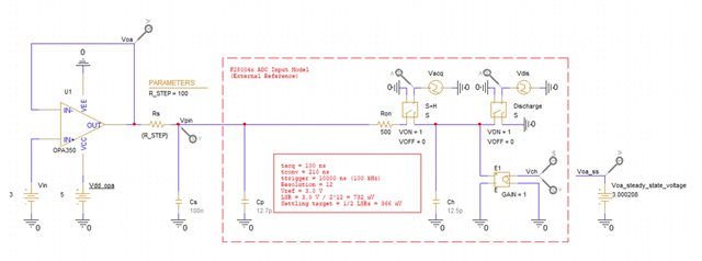
Here is the schematic of Circuit A:
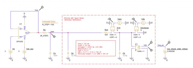
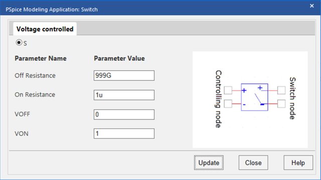
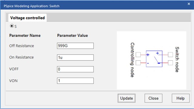
OPA350 was obtained using the PSpice Part Search tool. Capacitors Cs and Cp each have an initial condition of 3 V. Switches S+H and Discharge are identical. The settings of each switch are shown below:
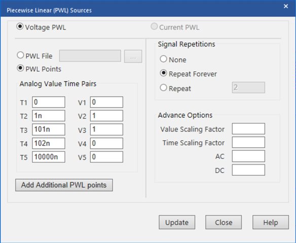
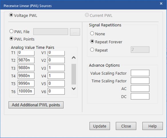
Vacq and Vdis are PWL voltage sources created using the modeling application. The settings of Vacq are shown below:
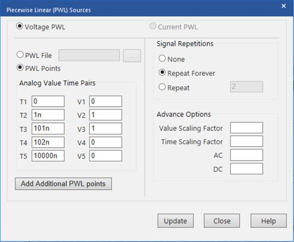
The settings of Vdis are shown below:

The simulation profile used is shown below:
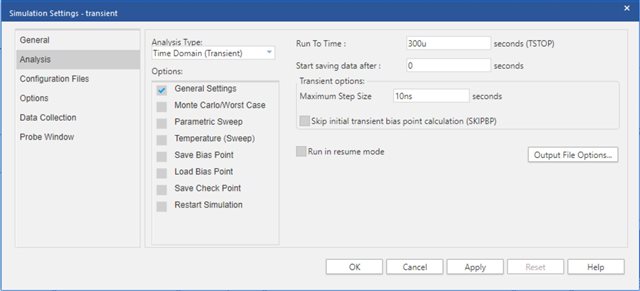
In the simulation profile, all Options were kept as default. The simulation results are shown below:
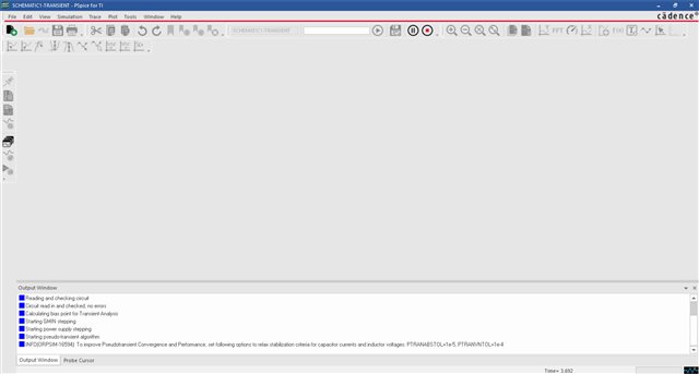
In this fashion, Circuit A does not converge.
Here is the schematic of Circuit B:
OPA350 was obtained using the PSpice Part Search tool. Capacitors Cs and Cp each have an initial condition of 3 V. Switches S+H and Discharge are identical. The settings of each switch are shown below:
Vacq and Vdis are PWL voltage sources created using the modeling application. The settings of Vacq are shown below:
The settings of Vdis are shown below:
The simulation profile used is shown below:
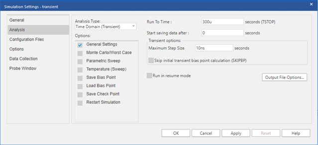
In the simulation profile, all Options were kept as default. The simulation results are shown below:
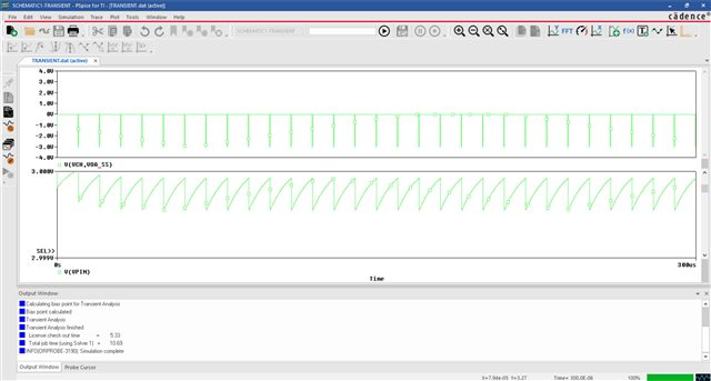
In this fashion, Circuit B does converge. Thus, two identical circuits with identical simulation profiles behave significantly differently.
As an additional note, the above simulation profiles both do not skip the initial bias point calculation. If I do skip the initial bias point calculation, both Circuit A and Circuit B converge. However, the results are significantly different as shown below:
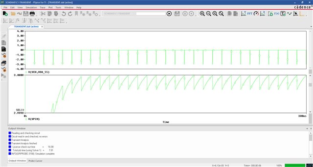
Skipping the initial bias point calculation introduces a droop on Vpin of about 13 mV at the start of data collection. Through additional testing, I believe this droop occurs because it takes the output of the op amp about 130 ns to reach its steady state value.
Why might Circuit A and Circuit B be behaving differently? Additionally, is it normal for skipping the initial bias point calculation to introduce a change like this into the simulation results?
Thanks,
James


