

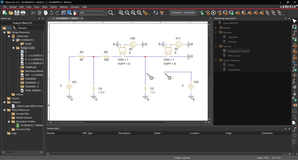
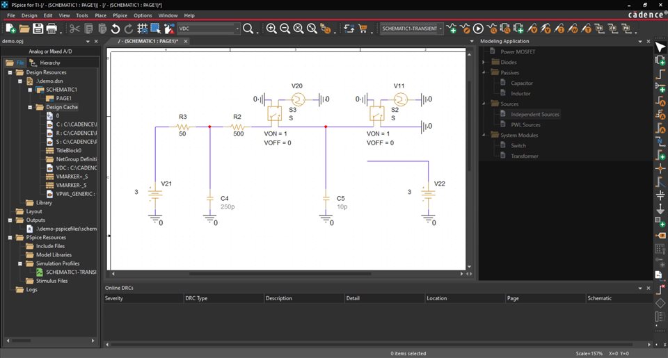
While using the PSpice for TI simulation tool, I noticed inconsistent behavior in a transient simulation. I've attempted to create as simple a circuit as possible that demonstrates this inconsistent behavior. The circuit schematic and initial state of the design cache are shown in the image below. I created the voltage sources using the modeling application. There are no initial conditions on any of the capacitors.
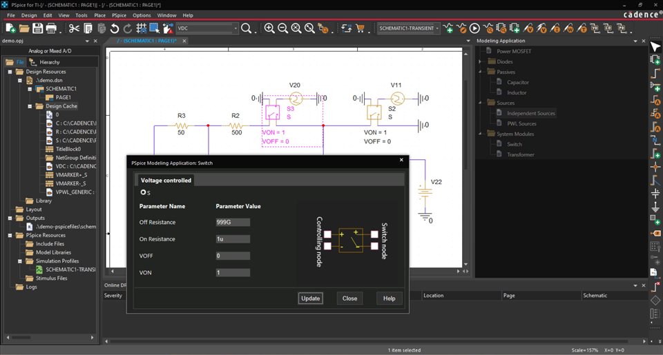
The switches S3 and S2 are identical. Their parameters are shown in the image below.
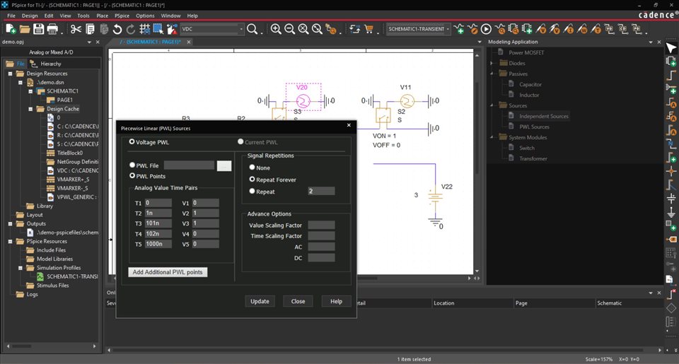
V20 is a PWL voltage source created using the modeling application. Its parameters are shown in the image below.
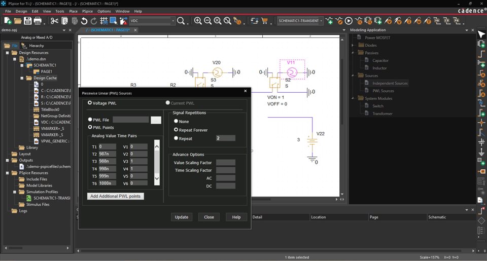
V11 is also a PWL voltage source created using the modeling application. Its parameters are shown in the image below.
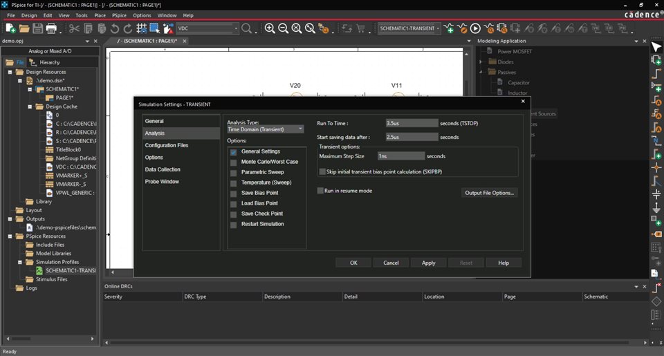
The simulation profile for the transient simulation is shown in the image below.
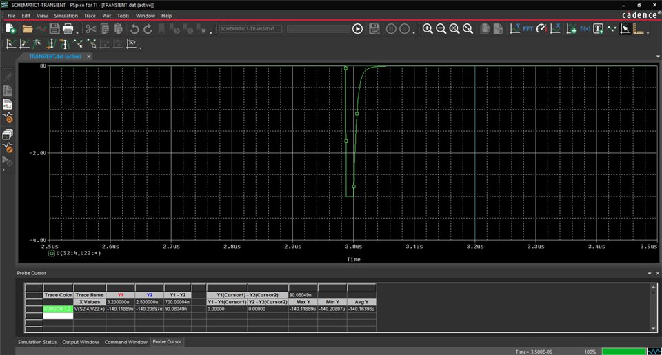
When I ran the simulation, I obtained the results shown in the image below. Note that the measured voltage at 3.2 us is -140.11889 uV.
I then cut a portion of the circuit from the schematic, cleaned up the design cache, and pasted that portion of the circuit back into the schematic. Doing so changed the order of the components within the design cache. I repeated this action until I observed different results from the simulation. The (identical) circuit schematic and (different) final state of the design cache are shown in the image below.
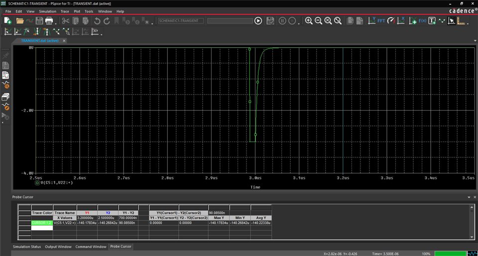
When I ran the simulation, I obtained the results shown in the image below. Note that the measured voltage at 3.2 us is -140.17834 uV.
Thus, the measured voltage at 3.2 us was different for two simulations with identical schematics. While the difference between measurements was on the order of tens of nV in this example, I previously observed a difference between measurements on the order of hundreds of nV in the example in which I originally observed inconsistent behavior. The original example included an op amp and some initial conditions that may have exacerbated the inconsistencies.
I have also observed other actions that can produce inconsistent behavior. While I chose to cut and paste portions of the circuit while refreshing the design cache, I have also noticed that the following can produce inconsistent behavior:
What might be the source of this inconsistent behavior? Is there a way to control / reduce / eliminate this inconsistent behavior?


