This thread has been locked.

If you have a related question, please click the "Ask a related question" button in the top right corner. The newly created question will be automatically linked to this question.

TIDM-1000: Simulation, hardware & system design tools forum

Part Number: TIDM-1000

Hi Team,

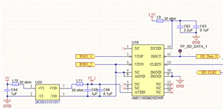
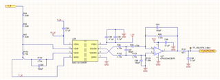
   1. In the case of TIDM-1000, the resistance RSH1 is used to measure the inductor current without the signal of Hall sensor. Can the hall sensor be omitted?

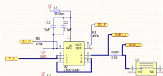
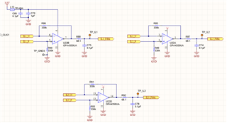
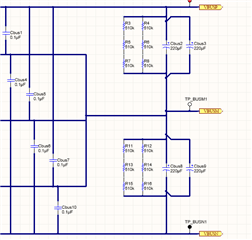
2. The output voltage VBUSP in the main circuit and  the V_ P in output voltage measurement circuit  should be the same terminal? Should the same name be used in the schematic diagram?

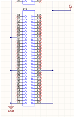
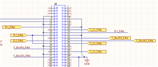
3. What's the use of J10?  J8 have 120 pins,Does 280049 also have 120 pins?


  • Why are both pin 24 and pin 31 connected to V_BusPM_Fdbk?pin 26 and pin 37 connected to V_BusMN_Fdbk?

  • Hi Fei,

    Sorry for the late reply due to holidays. 

    1. We provided two options for current sensing, hall senser with ADC and SDFM. What you pointed out is SDFM routine.

    2. They are the same. And we labeled them in the schematic. 

    3. The f2837x/f2838x controlcard(not the chip) has 180pins and J10 is part of it. 

    Regards,

    Chen