This thread has been locked.

If you have a related question, please click the "Ask a related question" button in the top right corner. The newly created question will be automatically linked to this question.

TIDA-01487: CAN repeater problem

Part Number: TIDA-01487

Hi TI,

I am trying to understand the design about TIDA-01487

Have some questions :

1. What is the relationship between delay time 210ns and "higher CAN data rates as 2Mbps" .

If my data rates only 1Mbps, best delay time is ?

2.My circuit test have some spike about TX1/RX1/TX2/RX2, but added filter cap will cause bus heavy easily. 

How could i understand this question, it's about  CAN data rates also?

thanks

JJ

  • Hi JJ,

    Thank you for using this reference design.

    To respond to your question.

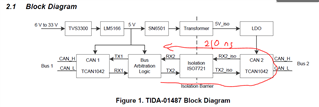
    1. To quote the TI Design guide: "The delay line unit has an asymmetric delay of the CAN bus line transition. This unit has only a delay of 210 ns from dominant state to resistive state and no delay from resistive state to dominant state. The asymmetric delay of 210 ns is needed to support higher CAN data rates as 2Mbps."

    To illustrate this clearer, here is a drawing of the 210ns delay.

    2. I don't understand your question/concern. Please explain what kind of issue you see.

    Thanks and regards,

     Thomas

  • Hi Thomas,

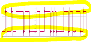
    The RX signal spike exceed 6.5V waveform as below.

  • Hi JJ,

    Thanks for sharing the screenshot.

    I cannot really comment why you see spikes on RX line, base on the available description.

    Is this caused by an improper GND connection of the scope probe? I think this is not related to TIDA-01487, but caused by either improper measurement, or something else in your circuit implementation, that you need to investigate further.

    Regards,

     Thomas

  • Hi Thomas,

    Thanks for your help!