This thread has been locked.
If you have a related question, please click the "Ask a related question" button in the top right corner. The newly created question will be automatically linked to this question.
Hi all.
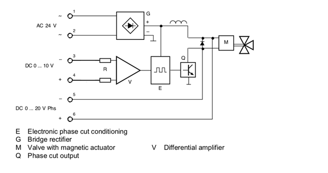
I need to design a new board in order to replace the original drivers for some HVAC's fluid control valves operating in the 0-20V DC range in phase cut mode. The steering method is an analog 0-10V DC that controls the amount of aperture of the valve in a quasi-proportional way (0-100%). I was thinking of using PWM method so I came across this thread and TIDA-00289 that as far I have understood uses only the enable pin to open/close the valve.
Could you please point me to the right direction to check if it can be done modifying the schematic?
I know it sounds a little bit vague but I need a starting point to begin.
best regards.
Hi Stefano,
What does the 'phase cut mode' mean? Do you mean these valves have multi-phases to control?
In DRV110, the HOLD and PEAK pins are used to set the hold current and peak current of a solenoid.
If the volves have multi-windings to control, they may need other controllers.
Best regards,
Jerome Shan
Hi Jerome and thanks for your reply. Phase cut method is a rather analogue "old" method of controlling the rate of the valve aperture (how much the plunger is pushed outside the solenoid) by using the AC frequency to cut every 10ms every time it crosses the 0V the current applied to the solenoid. It is basically a simple but very reliable method. Giving a 0-10V input You can linearly open the valve from 0 to 100%. I attach you the schematic. There is no feedback control (no way to determine if the valve has been actually opened or not) and no peak and hold mode. So I need to replace the circuit with a more modern circuit (feedback control/energy save method) and I came across the TIDA-00289 schematic. But I see it has a ON/OFF method not proportional way to control the solenoid. I was wondering if a PWM method can be applied to control the valve accordingly. Best regards and thanks.
Hello Stefano,
TPS274C65 is a high side switch that might be the right part here
- max operating voltage 36V, maximum current (all 4 channels) 5.2A continuous, so I guess they can directly drive the valve
- adjustable current limit with 10% accuracy, thermal shutdown
- integrated current sense ADC: 8.5 ENOBs, 125us update time, which can be used to save current
- can be operated with PWM frequency up to 1kHz
- SPI controlled
the PWM signal need to be generated by a simple MCU, which can be used also to read the current sense ADC outputs and adjusts the current accordingly.
simple MCU, like MSPM0L1306 integrates the required analog components to implement the difference amplifier and input signal chain.
If faster PWM is required, TPS272C45 can be used, however it doesn't include the ADC, so MCU ADC is required.
Please let us know if that goes to the direction you have in mind, and if you have further specific questions.
Kind Regards,
Ahmed
Ahmed, thanks a lot for Your valuable reply.
First of all may I ask You what are the parameters to choose the right PWM frequency? In actual circuit configuration the signal which is driving the MOSFET has a 10ms period spanning from 1% to 100%. so must assume 100Hz frequency. the valve is, at 100% driven by the voltage seen as attachment.
What do I need to consider when choosing the right PWM conversion?
Best regards and thanks
Hi Stefano,
I don't have full details of your requirement, existing solution waveforms, or the valve parameters so I'm not able to give a specific advice here.
On high level, and starting from the PWM of 100 Hz, you can generate the average voltage required by the valve, at the same time you will be sampling the current going to the valve using the ADC at higher speed, compare this to the desired current and adjust the PWM accordingly hence building a control loop with the help of MCU.
The analog part of the loop can be simulated using PSPICE. the TPS272C45 has a transient model, you might also use a model for the valve, and use a pulse wave generator to represent the PWM. this could help in understanding the loop dynamics and allows for designing a stable loop.
Best Regards,
Ahmed