This thread has been locked.

If you have a related question, please click the "Ask a related question" button in the top right corner. The newly created question will be automatically linked to this question.

TIDA-01504: Advice on resistor value setting

Part Number: TIDA-01504

Hello team,

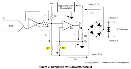
My customer and I have a question on resistor value setting of R3 and R4. Do you have any advice on decide R3 (or R4) value?

We understood that large R3 / R4 value is important. 
Best regards,

Shotaro

  • Hi Shotaro-san,

    You are right that it is important to size R3 and R4 larger, especially relative to R1 and R2, to ensure much of the loop current to flow through them, reducing power dissipation.

    The design mentioned in that TIDA project uses the following resistor values:

    • R1 = 26.5 kΩ
    • R2 = 102.4 kΩ
    • R3 = 1980 Ω
    • R4 = 20 Ω

    With a VREF of 4.096 V, this gives the Loop Current a range of 4 mA - ~19.5 mA depending on DAC code.

    I would recommend having your resistors similar to these orders of magnitude as good performance and accuracy was observed.
    You could choose either R1 and R2, or R3 and R4, first and then tweak the values of the other pair of resistors until your desired current range is found.

    I've also attached a quick excel sheet I made for easy calculations of Equation 3 that you posted, let me know if there are any issues with it.

    Thank you,
    Lucas

  • Hello Lucas-san,

    Thank you for the reply. We will utilize the quick excel sheet you attached. It is useful for us!

    In other examples on application note, R3 and R4 value is around 2kΩ and 20Ω, respectively. Do you have any idea why these values are these? (ex: R3=20kΩ and R4=200Ω should have an issue?)

    Best regards,

    Shotaro

  • Hi Shotaro-san,

    Those values of R3 and R4 were chosen to have a gain of ~100 which reduces the power dissipation, as a larger portion of the loop current will flow through them.

    For low power dissipation, it is important that R3 and R4 are orders of magnitude away from R1 and R2. 

    Using equation 3 from before, you can choose initial resistor values to give a high gain value, and then based on the desired current output of the circuit, you can solve for R1 and R2, and always tweak R3 and R4 if needed. (I assumed that the author of the TIDA chose 1980 and 20 ohms so the gain added up to a clean value of 100).

    P.S. I realized my excel sheet forgot to add the +1 to the gain, so I have updated it below and will remove the old attachment.

    Thanks,
    Lucas

    3666.TIDA-01504 Calc.xlsx

  • Hello Lucas-san,

    For R1~R4, we understood. Thank you for your support.

    Also how about R5? Do we have any guideline on deciding the value?

    Best regards,

    Shotaro

  • Hi Shotaro-san,

    If the customer knows the BUS voltage or Q1's Vce, they can use equation 6 to calculate a value for R5. (The 20 mA is the max V/I output of the circuit)


    In this design, they use a Vce value of 2 V and a R5 value of 60.4 Ω.

    R5 must be smaller than the (max output of U3 - 0.7 / 20 mA), in this case 60.4 Ω < 215 Ω.
    This means if it is over this amount, you may need to resize R4 or parts in the circuit.

    Let me know if there are any other questions!

    Thanks,
    Lucas

  • Hi Lucas-san,

    Thank you for the comment. My customer asked me additional question.

    If there is no R5 resistor, what kind of issue does occur? (Only R4 resistor, the circuit works well...?)

    Best regards,

    Shotaro

  • Hi Shotaro-san,

    I would recommend using R5 to reduce power dissipation, but if the customer observes the circuit working well without it and is within their specs, that should be fine.

    Thanks,
    Lucas

  • I hear that R5 helps reduce power consumption, but how does R5 work?
    I don't understand how R5 works in the circuit, so please let me know.
    thank you.

  • Lucas will respond after the US holiday weekend.

  • Hi,

    Adding R5 allows R4 to be a smaller value in Equation 6:


    Since R4 and R3 will be smaller, more of the loop current will flow through the BJT, allowing for less active power dissipation.

    Thanks,
    Lucas

  • Hi Lucas-san,

    I couldn't understand the part about reducing active power loss.
    I would like you to give an example of when R5=20Ω and when R5=0Ω, and compare the two.

    thank you.

  • Hi, 

    I apologize, I believe I had the power dissipation backwards, adding R5 may increase power dissipation slightly.

    R5 helps to stabilize the circuit connected to NPN, improving linearity and accuracy. It helps lessen the impact of noise and error from the OPA.

    Thanks,
    Lucas

  • Hi Lucas-san,

    I couldn't understand the part about "R5 helps to stabilize the circuit connected to NPN, improving linearity and accuracy. It helps lessen the impact of noise and error from the OPA.".
    I would like you to give an example of when R5=20Ω and when R5=0Ω, and compare the two.

    thank you.

  • Hi,

    If there is any resistance connected to the collector, the gain of the NPN will be - Rc/re (with re being the intrinsic emitter resistance)
    By adding Re of 20, this would be added to the re in the above equation, so now the gain is -Rc/(re+20).
    If a large modulation of Ic occurs, the denominator isn't affected as much since 20 Ω will outweigh re.

    Adding Re also provides negative feedback which can stabilize the circuit when the temperature changes. The temperature change causes Ib to rise, which increases the voltage drop across the Re, which in turn lowers Ib and helps stabilize the circuit.

    Based on my understanding, adding the resistor can help protect against noise at the collector and overall stability in unideal environments.

    Thanks,
    Lucas
