A related question is a question created from another question. When the related question is created, it will be automatically linked to the original question.
If you have a related question, please click the "Ask a related question" button in the top right corner. The newly created question will be automatically linked to this question.
my name is Ivan Goljer and I am a student at the Slovak university of technology in Bratislava. I have questions regarding to sensorless position/speed DC motor control (TIDA-01421).
1. Desciption of MCU function in circuit and explanation of equations in picture below.
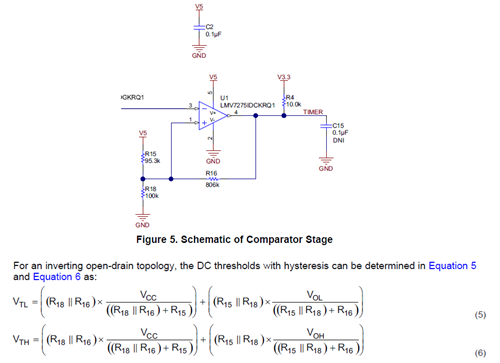
2. Explanation of equations 5,6, (especially parallel R18 and R16 based on picture).
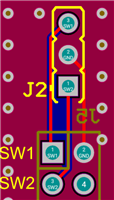
3. Explanation of J2 connection between PCB and MSP-EXP430FR6989.
4 Would it be possible to provide a code to understand the function of the MCU?
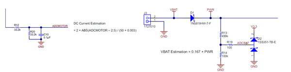
1. Those circuits are both resistor dividers to allow calculation of the average motor current (ADC motor) and battery voltage (ADCBAT). Both quantities are useful to know for algorithms determining pinch or obstacle detection, for example.
2. These equations assume the output of the comparator can be considered either Vcc or GND, depending on the state of the output. So for example if the output of the comparator is low (approximately GND) then R16 and R18 are in parallel from the non-inverting comparator input to GND.
3. Those signals could be used for switches if desired. They connect to GPIO pins on the MCU.
4. The primary goal of the TIDA-01421 design is to generate a TTL-level current ripple signal in hardware. See figure 3 in https://www.ti.com/lit/pdf/tidud30 . Therefore no software is required to operate TIDA-01421. The MSP430 is used only to provide a display of the up/down count of the output pulses.