- Ask a related questionWhat is a related question?A related question is a question created from another question. When the related question is created, it will be automatically linked to the original question.
This thread has been locked.
If you have a related question, please click the "Ask a related question" button in the top right corner. The newly created question will be automatically linked to this question.
Tool/software:
Hello
I have a TSW14J50EVM connected to an AFE58JD48EVM.
I can sample waveforms from HDSC Pro (version 5.20) properly but the trigger options do not work.
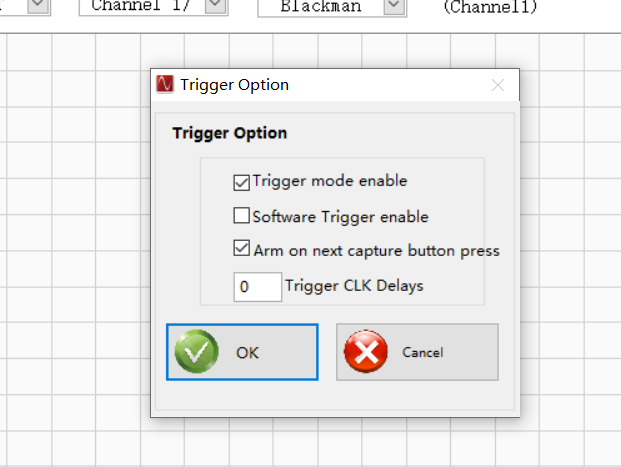
The trigger options are configured as follows:

I feed a 3.3V 100ns wide trigger pulse to TRIG_IN SMA connector but the capture does no start. HDSC shows “TRIGGERED ARMED” continuously but does not respond to my trigger.


After I select “trigger mode enable” and “arm on next capture button press”, and click generate “generate trigger”, HSDC waits a while and shows “no trigger occurred”.

I tried the following configurations, but they all failed :
User profile AFE58JD48_Custom_PLL_MODE_40x_No Demod_SubClass1 、
Firmware AFE58JD48.ini
Please tell me what needs to be done to make the external trigger work
Feng,
Unfortunately, external trigger with auto-rearm is not supported on the TSW14J50, due to the firmware not having the feature implemented.
On a separate note, digital input signals, such as Trig-In, should be 1.8Vpp.
See the following threads for more information:
Apologies for any inconvenience this may cause.
Shane Aspenwall,
We are not using an external trigger with automatic reset function. We need to receive external triggers from other devices or signal generators on the TSW14J50EVM and be able to work properly. According to the above steps, the final displayed result is' no trigger occurred '. I will send you the firmware I am using, can you tell me where the problem lies.
[ADC]

Interface name="TSW14J50RX_FIRMWARE"
Number of channels=16
Channel Pattern=1,2,5,6,9,10,13,14,3,4,7,8,11,12,15,16
Data Postprocessing=0:2,1:8192

\\operation:operand
\\operaion
\\0=bit shift
\\1=xor
\\2=and
\\3=or
\\4=not
\\operand
\\value(+ve if bitshift by right and -ve if bitshift by left)
\\E.g 0:-2,1:1024
\\bitshift by left 2 times and then xor by 1024

Number of Bits=16
Max sample Rate=125000000
Register_Config="-"
\\[Register Address]:[Register Value]:[Number of Bytes to be sent as]
DLL Version=1.0
Read EVM Setup Procedure="EVM Setup Procedure not available"
\\use <> as delimiter for newline
Menu Enable="Trigger Option"
Device GUI EXE Name=AFE58JD48 EVM
Device GUI EXE Port Number=6640
Device GUI EXE Path=..\AFE58JD48 EVM

[Version 1.0]


JESD IP Core_L=4
JESD IP Core_M=4
JESD IP Core_F=8
JESD IP Core_K=3
JESD IP Core_N=14
JESD IP Core_NTotal=16

JESD IP Core_CS=0
JESD IP Core_HD=0
JESD IP Core_S=1
JESD IP Core_SCR=0
JESD IP Core_Tailbits=0
JESD IP Core_LaneSync=1
JESD IP Core_Subclass=1
JESD IP Core_JESDV=1

\\Sysref Based Master Slave Trigger = 1

MIF Config= 0.5G to 8.0G:RX:RX_PMA_x40
\\List of Lane Rate Range,PLL Type and their MIF File names that needs to be configured,separated by ":"
\\These MIF Files need to be present under MIF Files Folder
Fabric PLL Counter = 0.5G to 8.0G:0x080202
Invert Sync Polarity = 0
 \\Invert Sync polarity, 1:invert; 0: do not invert
Invert Serdes Data = 0
 \\Invert Serdes Data, 1:invert; 0: do not invert
Transceiver Mode = 0
\\1:xcvr mode; 0: TX/RX only mode
Lane Mapping=lane0:0,lane1:2,lane2:4,lane3:6
\\Lane pattern for the LMF modes
Group 128 bits Flag = 1
\\Is Capture Trigger SMA = 1
Export Parameters = ADC Input Target Frequency
[ADC]

Interface name="TSW14J50RX_FIRMWARE"
Number of channels=16
Channel Pattern=1,2,3,4,5,6,7,8,9,10,11,12,13,14,15,16
Data Postprocessing=1:32768

\\operation:operand
\\operaion
\\0=bit shift
\\1=xor
\\2=and
\\3=or
\\4=not
\\operand
\\value(+ve if bitshift by right and -ve if bitshift by left)
\\E.g 0:-2,1:1024
\\bitshift by left 2 times and then xor by 1024

Number of Bits=16
Max sample Rate=125000000
Register_Config="-"
\\[Register Address]:[Register Value]:[Number of Bytes to be sent as]
DLL Version=1.0
Read EVM Setup Procedure="EVM Setup Procedure not available"
\\use <> as delimiter for newline
Menu Enable="Trigger Option"
[Version 1.0]


JESD IP Core_L=8
JESD IP Core_M=5
JESD IP Core_F=4
JESD IP Core_K=8
JESD IP Core_N=16
JESD IP Core_NTotal=16

JESD IP Core_CS=0
JESD IP Core_HD=0
JESD IP Core_S=1
JESD IP Core_SCR=0
JESD IP Core_Tailbits=0
JESD IP Core_LaneSync=1
JESD IP Core_Subclass=1
JESD IP Core_JESDV=1

\\Sysref Based Master Slave Trigger = 1

MIF Config= 0.5G to 8.0G:RX:RX_PMA_x40
\\List of Lane Rate Range,PLL Type and their MIF File names that needs to be configured,separated by ":"
\\These MIF Files need to be present under MIF Files Folder
Fabric PLL Counter = 0.5G to 8.0G:0x080202
Invert Sync Polarity = 0
 \\Invert Sync polarity, 1:invert; 0: do not invert
Invert Serdes Data = 0
 \\Invert Serdes Data, 1:invert; 0: do not invert
Transceiver Mode = 0
\\1:xcvr mode; 0: TX/RX only mode
Lane Mapping=lane0:3,lane1:2,lane2:1,lane3:0, lane4:5, lane5:4, lane6:7, lane7:6
\\Lane pattern for the LMF modes
Group 128 bits Flag = 1
\\Is Capture Trigger SMA = 1
Kind regard,
Feng Tao.
Feng Tao,
As I understand, you only need a single trigger between captures. I replicated your configuration (TSW14J50EVM + AFE58JD48EVM). Try the following:
1. Enable Trigger Mode

2. Connect Waveform Generator Source to J13 "EXT TRIG"
3. Setup Waveform Source -- 10us Pulse Width, 1.8Vpp, 1Hz. Output impedance should be set to 1M or Hi-Z. Output off. Reading DDR with the source off should cause the "no trigger occurred" error. It may require pressing twice, in case the DDR memory has already captured data.

4. Click "Read DDR Memory." Then, activate the trigger.

To verify the trigger started capture, I split the trigger output to the input of CH10 and captured the transient. The device has a LPF, so the pulse is not a square wave.

Hope this solves your issue!