- Ask a related questionWhat is a related question?A related question is a question created from another question. When the related question is created, it will be automatically linked to the original question.
This thread has been locked.
If you have a related question, please click the "Ask a related question" button in the top right corner. The newly created question will be automatically linked to this question.
Tool/software:
So i was researching TIDA-010086 Design Guide and schematic and i noticed discrepancies:
https://www.ti.com/lit/df/tidm733/tidm733.pdf?ts=1729188278028
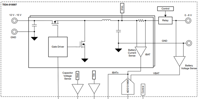
In the guide on page 4 there is a block diagram and there are 2 back to back FETs protecting the cell BUT in the schematic they are not present .
And now there is a fuse there.
What happened here and what is the correct reference?
Hi Dietrich,
Please check out the schematic of TIDA010087 where the protection relay is implemented.
100-A, Dual-Phase Digital Control Battery Tester Reference Design (ti.com)

Thanks,
Ethan
THX i dont see a point in having isolation page 6. I should be able to do it all with a normal high side gate driver?
I was considering some ideal diode drivers lm74700 lm74720 or lm74700d .
What do you recommend?I dont neem to be able to find high side gate driver ( preferably something that can deliver constant on state for prolonged periods of time)
Hi Dietrich,
You are correct about the isolation gate driver is not required in this application. In this design we implemented the protection circuit with isolated gate driver because the part can be enabled as low as 0V, so this reference design can still work when the battery is as low as zero volt.
The ideal diode drivers you mentioned above can worked as reverse polarity protection, but not for battery testing because turning on MOSFET at very low voltage might not be possible.
I was thinking something like protection for the cell itself since we will have multiple cells and all on the same GND directly connected and if 1 is inserted the WRONG way we want to prevent a short* reverse current* not even sure how to call it.
Basically there would be a huge current on that cell and we want to have some logic that opens the back to back FETs IF the cell is positioned correctly. we have some power rails that we can use , i dont intend to use the battery as the power source.
Do you think those ICs will work in this scenario? if not what do you recommend? Also is there a better solution? ( mechanical relay is not an option)
HI Dietrich,
Assuming your cells are not connected in parallel, and each cell is connected to a single DC/DC channel. If you connect a cell in a reverse direction, it will not affect other channels even though they share the same ground. The channel, where cell is connected in reverse directly, sees the negative voltage. Other channels don't see negative voltage.
Let us know if this clarifies your question.

Regards,
Shaury
Hi,
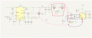
I was worried that the negative voltage will flow through my ESD protection diodes and effectively fry some chips , my INA219 in particular. there is also a mosfet through who internal diode i can see a patch here is a schematic ( assume cell is place the wrong way )

So:
pink path is through mosfet , the inductor will dampen a bit the current but just a few us i think
purple path is going to potentially fry my INA 219 , this one i can fix if i move it to the left of the red block but then again it is still a concern since not both pins support negative voltage
RED block is my attempt to fix this potential problem , i was referencing your TIDA 010086 010087 for this
Do you now understand my concerns? Also i know other channels will not be effected bu 1 channel but having that 1 channel get permanently damaged due to 1 such event is not an option.
NOTE: there is also a potential path through the main IC but i would like to fix this potential problem before it reaches that place
Hi Dietrich,
The current sensing path should be placed before your reverse protection mosfets. Like I said, Ideal diode driver can be severed as reverse polarity protection, but the controller will not turn on the mosfet at low battery voltage, it needs 0.5V to activate the controller from the source or drian and it can only detect 4V minimum from the anode. We don't have all-in-one controller to solve this issue.
So you cannot perform charge/discharge your load below this voltage and discrete control logic is needed.
![]()
In TIDA-010087 we built SSR with isolated gate driver to solve the issue above.
Let us know if you have any other question.
Thanks,
Ethan
hmm,
What id i reverse anode and catode and use it as a power switch ( i will power it from the main supply )
Or is there another solution?
Hi Dietrich
Yes you can use it that way and control the enable pin with external comparator. LM74502does not have reverse current blocking.
LM74502-Q1 data sheet, product information and support | TI.com
We also have power switch with integrated comparators and you can connect to battery directly.
TPSI3100 data sheet, product information and support | TI.com
Thanks,
Ethan
Hi Deitrich,
Yes, the synchronous power FET (Q25) in your schematic will not get immediately damaged when the battery is connected in the reverse. There is big inductor in the series with the battery.
INA219 ESD diode can be damaged. The minimum common mode voltage as per datasheet is -0.3V. You need to use an instrumentation amplifier with negative supplies to support negative common voltage like INA826. INA241A could also be an another option. It can survive up to -5V.
Regards,
Shaury
yea but someone need to react fast when that happens .
I was wandering is there this in TIs Chip selection
it is a gate driver https://ro.mouser.com/datasheet/2/408/TCK401G_datasheet_en_20191213-1289315.pdf
I will look at what your colleague posted and if i find it not suitable maybe a good old PPTC fuse will be enough , enable function is not so needed , safety for a long time is priority since i am sure someone will not check priority or polarity led fast enough .
I am sort of sure that Q25 can handle current while the fuse blows . INA219 remains a problem , ill check those INA you mentioned , ideally i would like something with I2C maybe a INA260 ? i didnt check if it also work in negative voltages , maybe something from that family....