This thread has been locked.

If you have a related question, please click the "Ask a related question" button in the top right corner. The newly created question will be automatically linked to this question.

TIDA-010087: TIDA-010087

Part Number: TIDA-010087
Other Parts Discussed in Thread: SFRA

Tool/software:

I am planning to implement control algorithm i.e., CC and CV loop. For that I need at what frequency we can implement. Related to this I found one design document of TI related battery tester with two channels.  The Document number is: TIDA-010087 (100-A Dual-phase digital control battery tester reference design). I go through this document, in that initially they find the frequency response of the plant, at this time the phase margin obtained as 6.66 Deg. Generally, the phase margin should be >45 Deg. Then we can tell system is stable. To increase the phase margin in that document they added the 2pole and 2zero compensator. At that time, the frequency mentioned as 15.625kHZ and the phase margin is 51.33 Deg. The same frequency is considered for the Control loop implementation(CC & CV) and ADC sampling frequency.  

My Doubt is the frequency mentioned is compensator tuned frequency or plant + compensator tuned frequency. Please clarify that my understanding is correct or I need to analyse in different way.

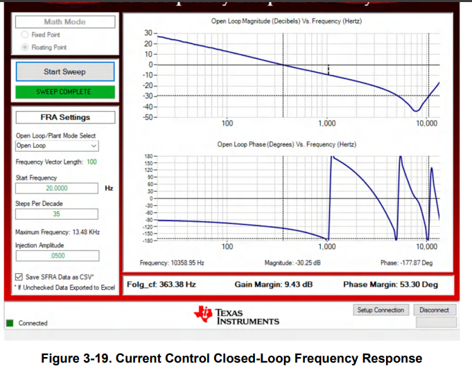
 After that again frequency response is shown and mentioned as open loop, that means compensator and plant in open loop is obtained and check the phase margin and all. Is it correct.?

In the same way I also tried to implement using MATLAB Software. Initially current to duty cycle transfer function obtained bode plot is implemented from that I obtained phase margin as 4.74 Deg. After that my transfer function is converted to continuous domain to discrete domain at my switching frequency. Then I implemented sisotool in MATLB to design the compensator. In compensator editor I added the 2-poles and 2-zeros to the system and tuned the compensator by adjusting the Gain and the phase margin obtained is 45 Deg and that time my frequency is 6.78kHZ. So I need to use this frequency as the control loop frequency and ADC sampling rate or the compensator obtained from the MATLB should add to plant and the overall transfer function should implement the bode plot and obtained the phase margin and frequency. This overall obtained plant + compensator frequency should I use for control loop frequency and ADC sampling rate.

Please clarify in my approach to design in better way.

  • Hi Bhaskar,


    Lab1 experiment in the reference design shows how to extract the plant transfer function. The transfer function is Iout/duty. This is an open loop system. There is no concept of phase margin for an open loop system. The plot shows that phase of the plant at 0dB gain, not phase margin.

    15.625kHz is ADC data rate. We are using a digital compensator. The digital compensator runs at the ADC data rate. You needs this to calculate coefficients for 2P2Z compensator. The compensator tuned frequency is 400Hz. At the 400Hz, OL plot(blue) becomes 0dB. See the below pictures. First picture shows compensator designer result. Second picture shows SFRA result for using designed compensation values in the c2000 firmware. Both show same result, 400Hz.

    I'm not familar with sisotool in MATLAB. What I understood, in your MATLAB example, you have a transfer function. You don't need to convert this to discrete domain. You can design an analog compensator first. If the analog compensator satisfies your requirements, you can find out the digital compensator values by using compensator sample rate, which is same as 15.625kHz. You don't need to use switching frequency.

    Your last question is should bode plot include compensator response? Yes. In the closed loop system, we study phase and gain margin of the loop gain. Loop gain is multiplication of all gains in the loop. This means that you need to use multiply plant response with compensator response to obtain the phase margin and zero crossover frequency.

    Let me know if you have any other questions.

    Calculated bode response

    Zero crossover frequency: 386Hz

    Measured bode response:

    Zero crossover frequency: 363Hz


    Regards,

    Shaury

  • Hello Shaury,

    Thank you for the explanation. 

    Application Report of TI SPRABX5–January 2015; in this clearly explaining that after generating compensator from MATLAB we can get the coefficients of 2pole and 2zero. So these coefficients can be used in C2000 digital compensator designer GUI to get the compensator sample rate. Like that can i use? If it is possible please tell the source or link to download the compensator designer GUI. 

  • Hello Shaury,

    How to calculate compensator tuned frequency. 

    If i am tuning my compensator where i am getting Phase margin and cross over frequency at particular value for the 2zero and 2pole compensator. Can i consider that as compensator sample rate. 

  • Hi Bhaskar,

    You can download the c2000-ware and c2000-digital power sdk for the compensation designer tools C2000WARE Software development kit (SDK) | TI.com

    Compensation sample rate is what you defined in your system. In our application we used ADC sampling rate same as control frequency, 15.652kHz. 

    Details of 2p2z calculation and phase/gain margin please refer to this thread: TMS320F280049C: Design/coefficient calculation of 2p2z controller parameters and their relationship with the continuous time-domain transfer function - C2000 microcontrollers forum - C2000Tm︎ microcontrollers - TI E2E support forums

    Thanks,

    Ethan