This thread has been locked.
If you have a related question, please click the "Ask a related question" button in the top right corner. The newly created question will be automatically linked to this question.
Hi,
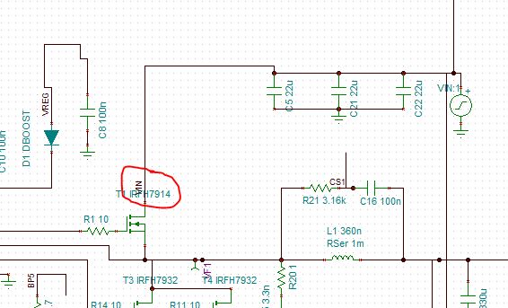
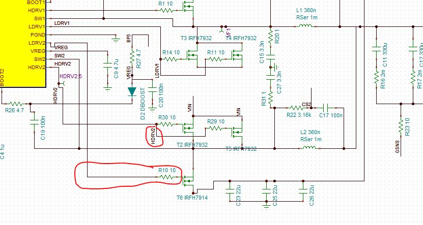
I am using TPS40140 for converting 12V to 1.8V in our design. To conclude on the design and various component values, I want to simulate the circuit in TINA. Using the reference circuit provided by TI for TPS40140 for 1.5V, I had my circuit designed as per the requirements.
When trying to do the Transient analysis, an error saying "Convergence Problem.Check the analysis parameters" occurred. I tried changing the parameters but of no use. The error keeps on repeating for different parameters.
Can anyone suggest how to resolve this issue. The schematic of my design is attached here.
Giridhar,
Finding convergence issues is very difficult. Could you provide your .TSC file? If not, could you tell us what parameters you have changed and if the convergence error changed at all?
Transient analysis convergence is usually controlled by the parameters marked with a TR, however, the basic convergence parameters may also be needed for the matrix to be solved correctly.
Hi,
Thanks for the response.
I am attaching my .TSC file along with this post/cfs-file/__key/communityserver-discussions-components-files/234/TPS40140_5F00_test_5F00_1V8.TSC
Also can you please let me know if there is any provision for current probing in TINA simulations.
Thanks..
Hi,
We are struck at this point of simulation. A response as soon as possible will be most helpful as we have to carry on with the rest of the design process.
Thanks.
Giridhar,
I am taking a look at this issue. I have not found a solution yet.
Giridhar,
I have found a couple of issues with the schematic. First is the Vin source:
What kind of VIN waveform are you trying to achieve? Normally, I would use a PWL to 12V with a fixed startup time and then a constant 12V. When I change this source, the simulation still does not converge, but when I add the VIN ID to the VIN wire so that all VIN labeled wires are now connected to VIN:
The simulation converges and finishes, but does not give the results you are looking for.
Apparently, you have switched the LDRV2 and HDRV2 connections and tied the VIN improperly to the lower half of the schematic. Based on the schematic picture you posted, HDRV2 and LDRV2 are not connected properly.
I believe that once you fix those connections, your simulation should run properly. Please make sure to add the VIN id to the wire connected to the VIN source or you will not have VIN at all of the connections.
Hi,
Thanks for the reply.
Adding the ID 'VIN' did resolve the issue. I was of the opinion that since the source is named VIN, any wire with ID VIN will be connected to it. But it wasn't.
Now after giving the ID VIN to the wire connected to source, it did work.
And regarding the VIN source, I was just trying the square wave with very large time period, which is same as 12V source till the time period and with some rise time.
And HDRV2 and LDVR2 interchanged, was during the process of schematic changes, we had attached the old .TSC file. We did change that before.
Thanks for your time and resolving the convergence issue.