Other Parts Discussed in Thread: TINA-TI, , LM25116
Tool/software: TINA-TI or Spice Models
(Please do not tell me to use WebBench, TINA Spice, etc.)
(Please do not respond only with links about "how to solve convergence errors", in general.)
Note: I'm far from a Spice expert.
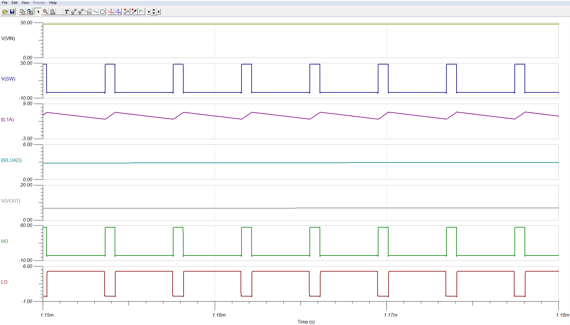
TLDR - I'm using (well, trying to use) the unencrypted Rev. C Transient Spice LM5116 model. I have already modified the model's syntax to make it run without syntax errors, but at present I am still plagued with "timestep too small" errors several hundred microseconds in. At this simulation time, the controller begins to enter DCM, and LO goes squirrely (that's the technical term) trying to determine when to shot the bottom FET off.
In my limited knowledge of Spice, I see this model uses IF statements to drive the HO and LO pins, which in turn drives FET gates, which in turn forces the Spice simulator to decrease its time step to solve abrupt nonlinear transitions, which in turn degenerates into a convergence error (i.e. "timestep too small".)
This probably goes without saying, but modeling the output HO or LO pins with a simple logical IF statement doesn't conform with the datasheet specifications of the LM5116. Can someone fix that?
Here's the full background:
I actually wanted to use the LM25116 model. I downloaded the unencrypted Rev. A Transient Spice model for the LM25116 and it was immediately unusable in LTSpice 17. I got errors that an initial "operating point couldn't be found" at a node internal to the model. Either it was node u1:_s1_mod-instance s:u1:1 or at node 28.
I tried all of the normal debugging steps:
- giving capacitors ESR values
- loosening current/voltage/relative tolerances
- reducing maximum time steps
- adding initial node voltages (e.g. at output)
- adding a path to ground through a high-valued resistor at each node
- ramping up the input voltage over several hundred microseconds
- telling LTSpice to just ignore the initial operating point with a uic statement.
The last one helped a bit, but at some intermittent time > 0 (usually only a few tens or hundreds of microseconds into the simulation) there would still be a "timestep too small" error (again, I assume something isn't converging.)
I contacted TI e-mail support, and told them that using another non-LTSpice simulator isn't in scope, and they sent me:
- this link (which tells me how to integrate WebBench to TINA), and
- this link (which says to use the 5116 model instead, because has been updated to fix some diode emulation issues, but suggesting the customer to apply those fixes to the LM25116.)
So I downloaded the unencrypted Rev. C Transient Spice model for the LM5116 and it was also immediately unusable in LTSpice 17. It was a little better, though, because it seemed to get past the initial operating condition more consistently without me having to use the ignore initial operating point (uic) statement. It still caused "timestep too small" errors a few microseconds in. Support and the FAE suggested loosening specific tolerance parameters (I mentioned in above list of debugging steps.) This got me far enough that I could see an error log from LTSpice about syntax that it apparently did not understand in the LM5116 model. Specifically:
- LTSpice didn't understand the use of a tilde ~ character as syntax.
- LTSpice didn't understand the use of double curly brackets {{parameter}}. Single curly brackets were fine {parameter}, but not double curly brackets {{parameter}}.
My research indicated:
1. the tilde ~ seems to be syntax that isn't universally recognized in Spice models. It is used once, on line 488 of the LM5116 model, with a "greater than" > in an IF statement. I removed it and replaced the "greater than" > with "less than" < and the syntax error LTSpice gave went away.
2. the double curly brackets are control how parameters are evaluated in Spice syntax. Nowhere did I see double curly brackets used, and just thinking like a normal programmer, I figured they may be redundant. I replaced all references to double curly brackets with simply a single curly bracket - the syntax error LTSpice gave went away. These double curly brackets occur in pairs in the LM5116 model on these lines: 500/501, 622/623, 626/627, 632/633, 639/640, 664/665, 671/673.
Question1: Can someone please confirm if the above two changes to the model syntax are benign? Or if they affect the model, how?
So with syntax errors gone, the simulation ran faster, but still had intermittent convergence failures (i.e. "timestep too small" at times > 0). However, now I believe I identified when these "timestep too small" errors happen - no surprise, it is when we start turning on and off a FET. Spice simulators already have a hard time calculating when nonlinear devices like FETs turn on and off - it makes it even harder when the LO pin decides to change its output every other time step (LO goes from on to off in a ps or less.)
The conditions I have are just a basic:
- VIN ramping up from 0v to 8v (or 16v) over 150us, and
- a light load current of 1mA or 100mA which turns on at 500us.
- As I mentioned, a current sense resistor between CS and GND
After VIN finishes ramping, I see this very erratic LO pin switching. It happens on both the rising and falling edges of LO, but it is especially bad on the falling edge. It begins as the converter transitions from CCM to DCM and continues during DCM regardless of whether the light load turns on at 500us or not.

This LO "jitter" forces Spice to decrease the timestep and causes convergence errors (i.e. "timstep too small") I believe.
Tangent: Support also sent me this link which doesn't appear to be relevant to this LO "jitter" issue I'm observing. But if anyone reading this needs help in knowing how to adjust TINA parameters to make square edges look more square, that link may help.
Back to LO jittering, I see this in the Rev. C LM5116 model:
- Line 77 shows a 1 Ohm series resistor between the CS pin and some internal node 39
- Line 87 shows node 39 is defined by an arbitrary voltage source
- Line 89 shows the arbitrary voltage source is defined by an IF statement.
My guess is that the logic for the special VRAMP features of this IC are easier to model with logical IF statements...but when you use a logical IF statement to drive a pin that connects to the real world, that's not going to model real-world behavior.
To prove this was the problem (partly to myself), I looked at the LM5116 datasheet, which says under a test condition of a 1000pF (1nF) load, the HO and LO pins have a typical rise/fall time in the 10-20 ns range. So I hung a 1nF capacitor at the LO node (in parallel with my low-side FET, which has much smaller Cg). I observed and measured the same jittery artifacts at the LO node, with ps and sub-ps rise/fall times.

The key thing in my circuit which causes the LM5116 to start this LO jitteryness, as far as I can tell, is that the sense resistor voltage (node is called "sense") going into the CS pin is transitioning between negative values and positive values about this time.
- Negative values indicate current is flowing from gnd, through Rsense, through the inductor, to the load (normally what we expect) and
- Positive values indicate current is flowing from the load, through the inductor, through Rsense, to gnd (not what we want - reduces efficiency - makes sense to turn off the LO pin at this time.)
However, since CS hovers around zero for some time with values of -uV to +uV, the LM5116 model's IF statement interprets these slight - to + transitions as sharp transitions, and then instructs the LO pin to turn from on to off (or vice-versa) very rapidly. This causes the convergence errors.
I tried to smooth out the - to + transitions on the CS pin side with the steps (below), but those attempts weren't successful. The bottom line is that the LO pin doesn't model the analog behavior the datasheet calls for.
Question #2: Can someone fix that?
Other debugging steps I tried to work around this:
- Added series ~40pH inductor to current sense resistor to attempt to reduce the jitteryness. Didn't help, since this isn't the source of the jitteryness.
- Added parallel ~600nF capacitor to current sense resistor to attempt to reduce the jitteryness. Didn't help, for the same reason as above.
- Attempted to look through model and see if there was some hysteresis I could easily apply to the CS input. There is no such switch I can see where it is obvious that an additional hysteresis parameter would help, because this pin's function is coupled with other RAMP features of this device.
Please note that there was switch node resonant ringing at one point, but that was unrelated to this issue. That switch node ringing is mentioned in the LM5116 datasheet, so it is an analog (i.e. real world) effect that was being predicted in my simulations. Per the datasheet's recommendation, I added a snubber circuit to the switch node and it went away.