This thread has been locked.

If you have a related question, please click the "Ask a related question" button in the top right corner. The newly created question will be automatically linked to this question.

PMP7294: Transformer winding turing ratio for 36 in and 24V 4A out ?

Part Number: PMP7294

Hi,

We would like to use PMP7294 for 36V in and 24V 4A out.

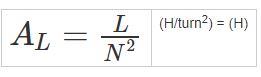
May i have your suggestion for transformer winding turing ratio primary winding : 2nd winding : AUX winding ?

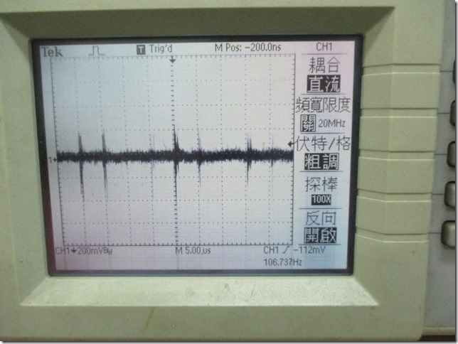
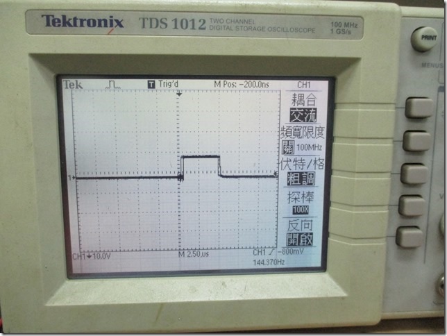
Also because the 36V input ( is gererated by LM5122) might have 750KHz ripple on it. Do we need to add some filter to remove those 750KHz ripple before the 36V goes into PMP7294 circuit?

Thanks!

  • Hi

    Thanks for your interest in TI's products. I have asked one of our applications engineers to take a look at this and you should see a reply within a day.

    Regards

    Peter
  • Hi Peter,

    We also see PMP10861 looks more suitable.

    The requirement as below, do you think PMP10861 can meet below configuration?

    1. Input : 10.8V ~ 26.4Vdc

    2. Output : 24.5Vdc : 4A

    Thanks!

    PY Tsai

  • Further question on PMP10861

    The reference design schematics show 320uH transformer, but the BOM show the trnsformer spec is 40uH. We would like to confirm which one is correct?

    Also may i have your adivse on for the formular for calculating the Transformer's winding ratio and the size of the core of the transformer?

    Thanks!

    PY Tsai 

  • Hello PYT sai,

    I would like to direct you to Power stage designer tool from TI. I have attached the file where you can play with the values. The attached file has your design parameters already and what I think your system should look like, below are the links to both.

    NOTE: the switching frequency of the UCC2897A from the Daughter card is 175KHz for these calculations, you may vary it according to your spec.

    For the turns ratio: as per the PSD tool it should be 1:2:1, however again you can vary the values for spec and get other results too.

    As far as the filtering is concerned, you do not need a filter for the 36V input to PMP7294 because there is a Ci (Input cap) which will do the filtering. 

    Thanks,

    Sonal


    ACTIVE_CLAMP_FORWARD
    30
    36
    24
    4
    175
    0.05
    80
    70
    20
    0.65
    150
    25

  • Hi Sonal,

    We had down loaded the tool and the attachment is our configuration. Would you help review below points? thansk!


    1. our design the Inductor current ripple will go up to 60%. Is this looks OK? 

      Our transformer now the Lsec is 396uH slightly higher than the tool's calculated value 256uH. Do you think it is ok?

    2. Turn ratio 0.25:1 is look ok? How about aux is it still ok primary : aux = 1:1 ?

    3. My configuration the Magnetization current will go up to 15%, is this ok?   

    4. The difference between choose inductance for transformer and choose inductance ? (are they minimum and maximum value)

      We use 40uH for choose inductance ok ?

    5. Is the calculated Lsec maximum value ?

    Thanks!

    ACTIVE_CLAMP_FORWARD
    10.8
    26.4
    24
    4.2
    175
    1
    60
    66
    15
    0.25
    16
    44.8

  • Hello PYTsai,

    Please find my comments below:

    1. Inductor ripple looks reasonable at 60%.
    2. I suggest a turns ratio os 0.15:1 to maintain your magnetization current and inductor ripple%. The aux ratio will be 1:1.
    3. The magnetization current is going up to 16.41% at worst case.
    4. Choose inductance for transformer: is the magnetizing inductance (Lm), choose inductance: is the value for L1.
    5. With 40uH of choose Inductance, you will end up having a Current ripple of 73% instead. 50uH will be sufficient to keep you within your current limit at worst case.
    6. All these calculated values from the tool are the recommended values, you can always change the values and play with the waveforms to see how much margin you can consider.

    Thanks,

    Sonal

    ACTIVE_CLAMP_FORWARD
    10.8
    26.4
    24
    4.2
    175
    1
    60
    66
    15
    0.15
    21
    50

  • Sonal,

    Thanks! iVery clear.

    Just to clarify the turn ration. My understand is primary : Aux turn ration = 1:1, is it correct ? thanks!

    PY Tsai

  • Hello PTsai,

    Yes the turns ratio for Pri: Aux is 1:1.

    Let me know if you have any other questions regarding the design.

    Regards,

    Sonal

  • Hi Sonal,

    We had done the PCB and had build the transformer base on above discussion. The turn ratio of our transformer is Primary : 2nd : Aux = 4:26: 4 which is the same as your suggestion. The choose inductance we are using now is 45 uH.

    Some question would like have your input.

    Question 1:          

    Test condition: Input 10VDC,  output 24.4V 0.2A. Q1 waveform as below (refer to PMP7294 schematics).

    - At this condition the circuit seems works fine. But when we increase the output current the circuit shot down.

    - Also if we keep the output current at 0.2A and increase the input voltage the 12VDC the curcuit also shut down.

    Do you think below waveform looks OK ? (the ON duty looks > 70%)


    Question 2:

    Test condition: input 10VDC, oout put 24.4V 0A. The circuit works fine. The we keep the output current at 0 A and then change the input voltage from 10V to 16V. The cirtut still works fine.  Q1 waveform (refer to PMP7294 schematics). is below Waveform looks OK?                    

    Question 3:

    Test condition: input 10 VDC, output 24.4 V/0.2A. We measure AUX (D202) waveform (refer to PMP7294 schematics) shown below. Is there any requirement for AUX voltage level? We would like to know if below AUX waveform looks good.

    Question 4: we are using 100K ohm for RON and 90.9K ohm for ROFF (copy PMP7294 value). Are these two resistor looks ok for my current circuit?

    Question 5: Aobve discussion, i saw you mentioned 175KHz switching freq. Do we need to adjust this switching freq?

    Thanks!

    PY Tsai

  • Hello PY Tsai,

    Please explain what do you mean by shut down? Also, I would like you to check if UCC2897A is hitting any Overcurrent or Overvoltage limit which leads the controller to stop working. Checking voltages at LINEUV, LINEOV, CS and Vref will be a good starting point.

    To answer your Question4 and 5: RON value determines the internal charging capacitor's charging current. and this with ROFF determines the operating frequency and the Maximum duty cycle(operating). Section 8.3.1.3 od the datasheet will help you calculate these values for your design. If you want the switching frequency to be 175kHz you will have to calculate RON and ROFF for your design.

    Kind Regards,

    Sonal


  • Hi Sonal,

    Thanks for the answer, we will go check LINEUV, LINEOV, CS and Vref .

    Sorry do not make it clear, the shut down, i mean UCC2897A out put no switching.

    It is clear i understood RON ROFF and frequency setting now.

    1. We found this probably the the cause. UCC2897A Vin requirement is 18V as shown below. My Vin is now 10V, do you think will it work? or i should do a voltage doubler to double it to > 18V then feed into the Vin pin of UCC2897A (like the implementation on our reference design PMP10861)?

    2. VDD 10V looks ok, is it ? thanks!

  • Hello PYTsai,

    1. It is very important to follow the recommended values on the datasheet. I strongly suggest that you should provide a Vin to the controller of 18V or above. A voltage doubler is a good option to continue with. 
    2. A 10V VDD looks good.
    3. In order to help you calculate the RON and ROFF, attached is a calculator tool that we use. Please use this tool for efficient results.
    4. I noticed from your previous question2 (attached image) the switching frequency looks overlapped over time, please adjust your trigger level in order to capture better waveform.

    5.In reply to question3 D202 is not the AUX voltage. AUX voltage is VGS of Q2 from the PMP7294 schematic. This function drives the aux-clamp of the             MOSFET when the PWM switching is OFF the MOSFET is HIGH. It is a high-current gate-drive output for the auxiliary switch to implement the active-        clamp operation for the power stage.

    I hope this helps.

    Thanks,

    Sonal

    UCC2897_SW.xlsx

  • Sonal,

    We added Vin voltage doubler circuit to the board and now for input voltage from 10.8V ~ 14V it can stablly get 24V out with current below 500mA.

    For Vin > 14V the UCC2897A shut down (no voltage at VREF and the output no switching)

    The duty cycle from scope we saw now is 69%.

    I use the calculator that you provide and input the RON (100K) ROFF(91K) RDEL(10K) and i see the DMAX = 67.7%

    the turn ration we are now is Pri:2nd: Aux (Bias) = 4:26:10.

    The turn ratio for CT is 1:100.

    May i get your help review above condition and hellp give us some suggestion where might be wrong with our circuit?

    Thanks!

  • Hello PYTsai,

    To clarify, the voltage at pin Vin of UCC2897A will be 21.6-72V. Also, the turns ratio looks a bit odd, please find attached the Power Stage Designer file I would recommend using this tool for turns ratio calculation. Now, the duty cycle looks well within the operating limits of the controller. 

    The reason behind UCC2897A not switching might be a couple of reasons: I would like you to check the potential at CS, LINEUV, LINEOV, FB and also VDD and make sure that the values are within the limits as recommended on the datasheet at the condition when it stops switching.

    Let me know if this helps.

    Kind Regards,

    Sonal

    ACTIVE_CLAMP_FORWARD
    21.6
    72
    24
    4.2
    175
    1
    60
    66
    15
    0.3
    70
    45

  • Hi Sonal,

    Now we fixed the turn ration 1:3.3:1. When shut down happen, we measure below value and also the CS and AUX waveform. Any more information we need to check ?  thanks! 


      Line UV = 1.8V

      Line OV = 0.38V

      FB = 5.0V

      VDD = 12.2V

    CS Pin waveform


    AUX waveform


  • Hello PYT Sai,

    I can clearly point out two problems with the data above:

    1. Your LINEUV is 1.8V however, the max LINEUV is only 1.27V as per UCC2897A datasheet. I would suggest redoing the calculations for resistor RIN2, RIN1 on page 31 under section 9.2.2.5

    2. Also, just to point out the FB voltage of 4.5V results in full-duty-cycle (Dmax=74%) operation. I would like to draw your attention to section 8.3.1.9:FB.

    I hope this will help. Let me know if you have further questions.

    Thanks,

    Sonal

  • Hi Sonal,

    Thanks very much for your great support. We finally make it works.

    Two more questions need your help:

    1. For the transoformer, is there any formular to calculate the needed inductance per turn ? 

    2. Our circuit now (same as PMP7294 circuit). when no load power on, the output can stable at 24.4V.

         But if we increase the load to 1A, the output will decrease to 12V.

               if we increase the load to 2A, the output will decrease to 10V.

         which part of the circuit should we do the fine tune (the transformer we are using now is Prim:2nd:Aux = 4:12:4. the transformer inductance for primary side is 

          (2 uH/Turn)*(4 turn)^2 = 32uH.

    Thanks!

    PY Tsai


  • Hello PYT sai,

    1. The inductance per turn is represented by AL, and the relationship of the inductance and the turns ratio is given by the formulae:

    2. The problem here as I can see is the FB loop not regulating the Vout. Now one possibility can be that when the control loop tries to regulate the Voltage and ends up increasing the power instead at no-load. Can you please provide me with a Vout Vs load current curve for a better understanding of it.  Another thing to point out here is since the Voltage drop from 1A to 2A load current is 2Volts this suggests that the resistance at Output is high, you can try to reduce its value for better regulation in meantime.

    Thanks,

    Sonal