My last thread has been locked ( I did not have access to a computer for a long time ) and I'm sorry to create new thread but I need a help.
I built a sensor based on your PCB and I need to test it now. I received data and I am not sure that my sensor works good.
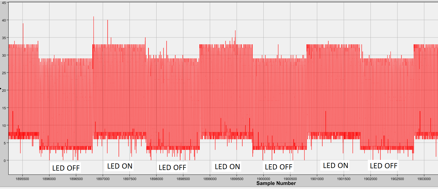
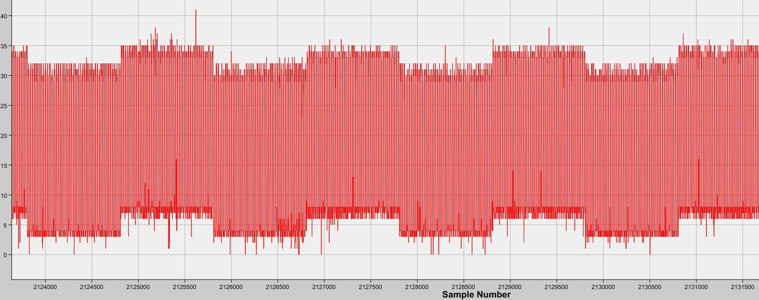
Enclosed you will find screens of graphs with raw ADC samples. I do not know if received data are valid, because I did not find in guide user sample screens.
I did not run the firmware included with the TI design, because I need to use Nucleo STM32F4 with your PCB and these graphs were made by a loop 'while' and were drawn by program TelemetryViewer.
Before I use your algorithm, I'd like to know whether my samples are good.

Please for information on it.