This thread has been locked.

If you have a related question, please click the "Ask a related question" button in the top right corner. The newly created question will be automatically linked to this question.

TIDA-00555: Dual output isolated DC supply

Part Number: TIDA-00555
Other Parts Discussed in Thread: AMC1100, , AMC1311, AMC1301, ADS131E08, MSP430FR5869

Hi,

I see the isolated power supply provides two outputs in this design: -6V_WSH and +5V_WSH, which are regulated to -5.0V_WSH, and +5.0V_WSH. The positive +5.0V_WSH is used to supply the AMC1100. But the only application of -5.0V_WSH is to limit the inputs of the AMC1100 between -5 to 5 by using DESD1P0RFW-7. Is this a true statement?

If yes, if we do not want to protect the AMC1100 in this way, then we should be able to use a cheaper design and only use one positive value (+5.0V_WSH) for the isolated power supply. Is the second statement true?

Thank you so much for your time.

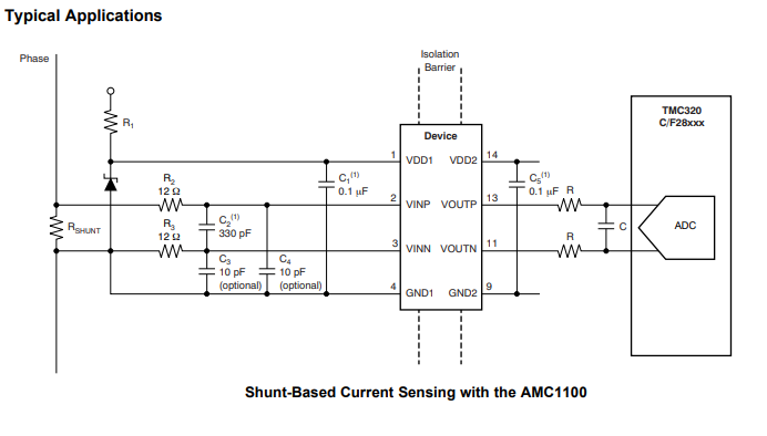
  • The main reason of my question is the application note of the AMC1100. In this document there is a typical application guide, which does not use the DESD1P0RFW-7 for the VINP and VINN.

  • Hello 

    I see the isolated power supply provides two outputs in this design: -6V_WSH and +5V_WSH, which are regulated to -5.0V_WSH, and +5.0V_WSH. The positive +5.0V_WSH is used to supply the AMC1100. But the only application of -5.0V_WSH is to limit the inputs of the AMC1100 between -5 to 5 by using DESD1P0RFW-7. Is this a true statement?

    Correct.

    If yes, if we do not want to protect the AMC1100 in this way, then we should be able to use a cheaper design and only use one positive value (+5.0V_WSH) for the isolated power supply. Is the second statement true?

    Yes.   Just to add, the protection approach depends on the application and performance requirements.

    One of the approach could be as below 

    What is the target end equipment or product where you are planning to use AMC1100 ?

    TIDA-00555 is targeted for grid applications. If this is a grid application, we have many other designs that you can view through the TI.com application path.

    http://www.ti.com/applications/industrial/grid-infrastructure/overview.html

    Thanks

    Sreenivasa 

  • Thank you for bringing up AMC1301 as well. The product we are currently working on is a grid connected rectifier. We are investigating different ICs and design, to find the best solution for our application. We already tested AMC1301, for AC and AMC1311 DC measurements. Now we want to test AMC1100.

    As you can see in the above picture, right after the AMC1301, the designer used a pull-up OPAMP (OPA2188AID) to range the output between 0 and 3.3V for the microcontroller. But here in TIDA-00555 there is no pull-up OPAMPs used to range the output of the AMC1100 to the 0-3.3 V for the micro controller. Could you please explain the reasoning behind it? 

    Thank you.

  • Hello 

    God to know the product you are working. 

    The signal scaling depends on the ADC being interfaced to.

    The isolation amplifiers provide a differential output and in TIDA-00555, The output is interfaced to ADS131E08, delta-sigma ADC with differential input. 

    In short, if you have a ADC with differential input up to +/- 2.5V, you can directly interface the isolation amplifier output. 

    Thee are resources for application related to AC/DC or DC/AC for EV/Inverters which may be of he;p for you.

    http://www.ti.com/applications/industrial/grid-infrastructure/overview.html

    Thanks

    Sreenivasa 

  • Thank you for the reply. Is there any code sample written for MSP430FR5869 for power and energy metering purposes? 

  • I want to use the TIDA-00555 with the second option: OPTION 2 MSP430FR5869.

  • Hello Mohsen Aleenejad

    Glad to know that you could select the MCU based on the TIDA-00555 design guide. MCU solutions provide an optimized host solution with internal differential ADC providing direct connect to the output of the isolation amplifier..

    Please see below the configuration we used with the MCU.

    Interface to MCU: An onboard MCU with a 12-bit differential input has been provided. When using the MCU, the common-mode voltage is configured to 1.29 V.

    Good luck for your project. 

    Please open a new E2E thread with the MCU number rather than the TI design number to receive wider support with respect to any queries you may have while designing with the MCU.

    Thanks

    Sreenivasa 

  • Thank you so much for good wishes. I'll open a new E2E for the MCU sample code. But I have another question before get this resolved.

    7.2.4 Accuracy Testing With AMC1100 Interfaced to MSP430FR5869

    1) The input of AMC1100 is set to a maximum of 61% of 175 mV, which is 0.105 V. Why o 61%? Is this because of he limited input of the MCU ADC to 0-2.5 V?

    2) In Table 30, It is netioned if this is an AC current. 

    3)  If that is AC current, for current: 34.8 A, the input of AMC1100 is 0.105 V then the output is 0.84, which is almost same as EXPECTED OUTPUT  mentioned in the Table 30. What if the current is -34.8 A. The output would be -0.84? I want to know the range of signal that goes to ADC of MSP430FR5869. 

  • Question 3 has been updated.

    3)  If that is AC current, for current: 34.8 A, the input of AMC1100 is 0.105 V then the output is 0.84, which is almost same as EXPECTED OUTPUT  mentioned in the Table 30. What if the current is -34.8 A. The output would be -0.84? I want to know the range of signal that goes to ADC of MSP430FR5869. Is that between -0.84 to + 0.84 or it's between 0.45 to 2.15? 

    Thank you so much for your time.

  • Hello Mohsen Aleenejad:

    Please note that AMC1100 is differential amplifier. For the AC input, with a common mode of 1.29, the output swings above and below.

    Also for the ADC, you will always consider the peak value as the input. 

    AMC1100 provides a differential gain of X8. This would imply an approximate voltage of 1.29 + 0.6 and 1.29-0.6 = 1.89 -> .71 for .105 RMS input.

    For AC input you will have the phase and the direction of the swing depends on the phase. RMS value remains same irrespective of phase.

    It would be best for you to simulate or have an EVM ordered to experiment.

    is the a product that will be sold in the market to customers?

    For any of the AMC related queries, it is best to open an AMC1100 thread to get wider answers.

    Thanks

    Sreenivasa 

  • Thank you so much for your reply. 

  • The reason I asked this question was my previous experience with AMC13051. In the datasheet of the AMC1301, you can see the output common-mode voltage is 1.44V, but for the ac current sensing purposes with shunt resistor I couldn't see this CM voltage, it was too much smaller than this value. Thank you for your time BTW.