


Part Number: TIDA-00817
Hello. Thank you for your kind help in the thread below, the problem is solved finally.
https://e2e.ti.com/support/tools/sim-hw-system-design/f/234/t/887682
Briefly, 12V battery's voltage should be over 12V. In the previous condition, mine was 11.X V.
In this thread, I have a question for Active Balancing Switch Matrix.
1. In 16-Cell Li-Ion Battery Active Balance Reference Design, which is tidubz7 document, p10, it is explained by this,
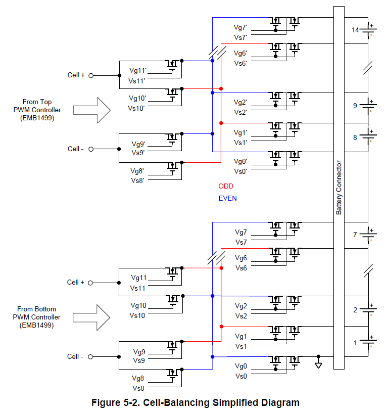
"To have multiple EMB1428Q polarity buses connected to a single EMB1499Q secondary circuit,
an additional switch matrix must be placed back-to-back in the polarity selection circuit to extend the voltage
rating of the FETs to full module voltage."
In this part, I'm confused about which period should be biased full module voltage.
In this architecture, only one cell is charging or discharging by active balancing.
Could you explain more details about the part above?
2. Due to battery testing system's specification, I couldn't use the whole 16 cell in series fully.
Is there any way that I can test only for 3 cells? or 1 module?
I always appreciate your help.
Thank you.
