This thread has been locked.

If you have a related question, please click the "Ask a related question" button in the top right corner. The newly created question will be automatically linked to this question.

TIDA-00951: Clamp delay time explanation

Part Number: TIDA-00951

Hi,

I have couple of questions on the boost mode,

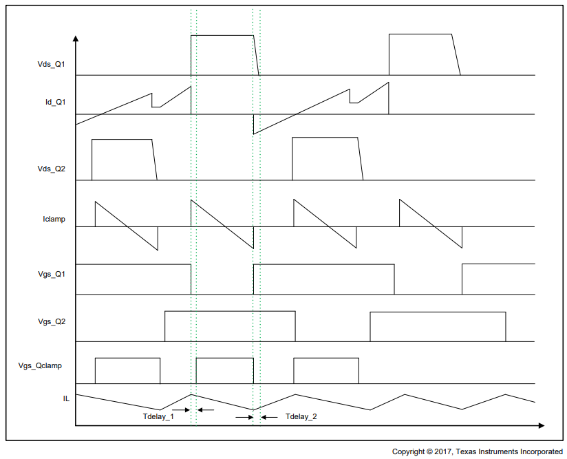
  • What is the purpose of delay_1 and Tdelay_2 ?
  • there is need to be ZVS is the transistors on the low side?

A very large power losses are created on the transistors during the "power boost" of 500W.

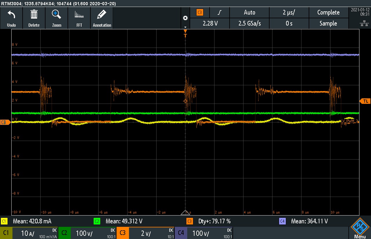
Another issue that i am facing is that i can see a lot of noise on the tida 00281 LV1 and LV2 leg, therefore the signal at the output of the DSP, I an suspect that there is an issue with the buffer between the DSP and the transistor. can you please assert me if this noise is normal (Orange signal)?

Thank you and Best Regards,

Michael

  • hi, 

    Tdelay1 is for Q_clamp ZVS, Tdelay2 is for Q1 and Q3 ZVS. Please refer to the discription in page9 of 6.3.1.2

    you can capture the hotest transistor by thermal testing, then you can double check the switching process of that transistor, it is large possible will find the root cause of power loss.

    The noise on the output of McU board should be introduced by hard switching. so your transistors must be operating on non-ZVS condition, and have large oscillation on its Vds. 

  • Hi,

    Thanks for the answer,

     "The noise on the output of McU board should be introduced by hard switching. so your transistors must be operating on non-ZVS condition, and have large oscillation on its Vds. "

    is it normal?

    BR,

    Michael

  • Hi, Michael

    The noise on your figure looks a little bit large, if you have used the least probe loop and well ground connected. This should be abnormal.